
Parallel tube burner with improved cooling and reduced size

Active Publication Date: 2010-04-22
CHAR BROIL
View PDF13 Cites 23 Cited by
  • Summary
  • Abstract
  • Description
  • Claims
  • Application Information

AI Technical Summary

Benefits of technology

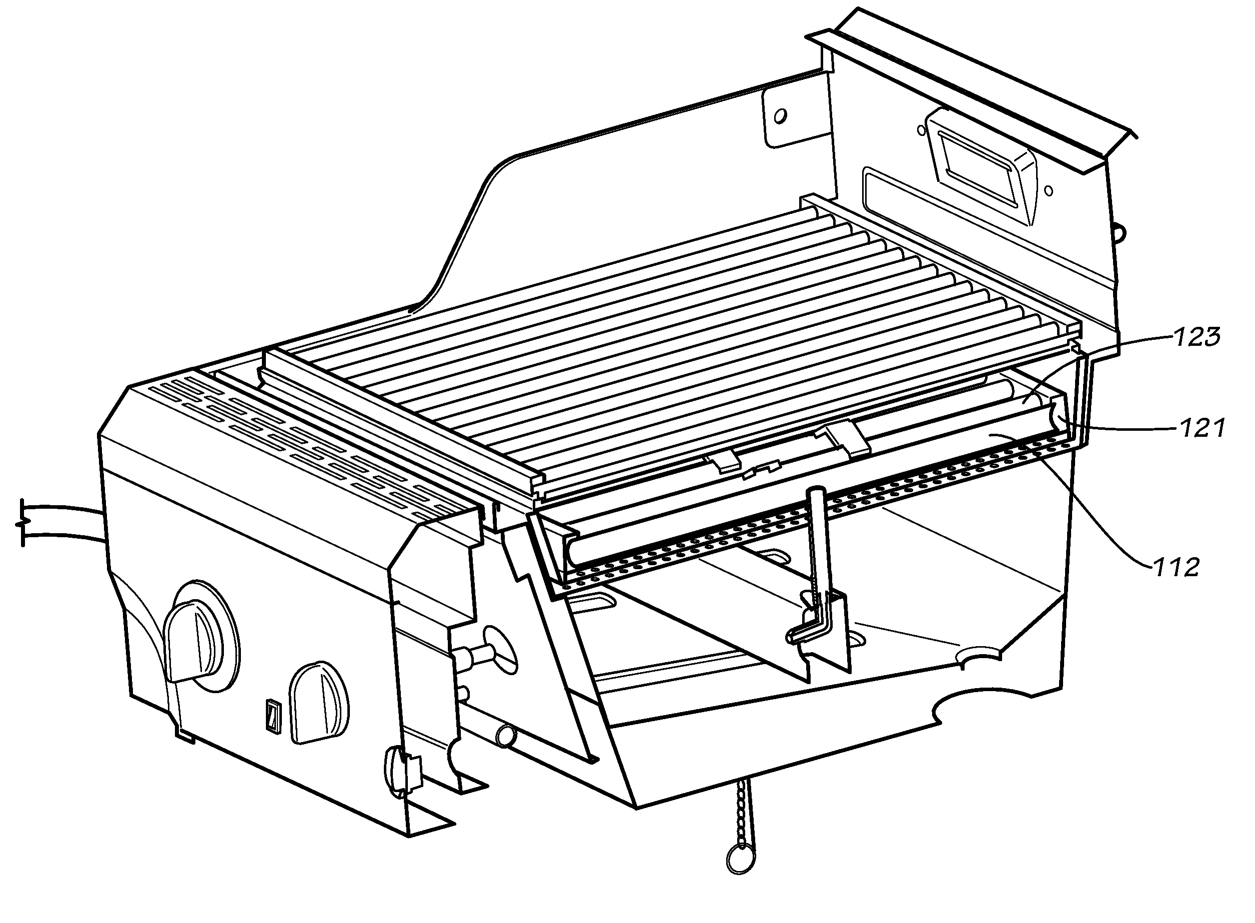
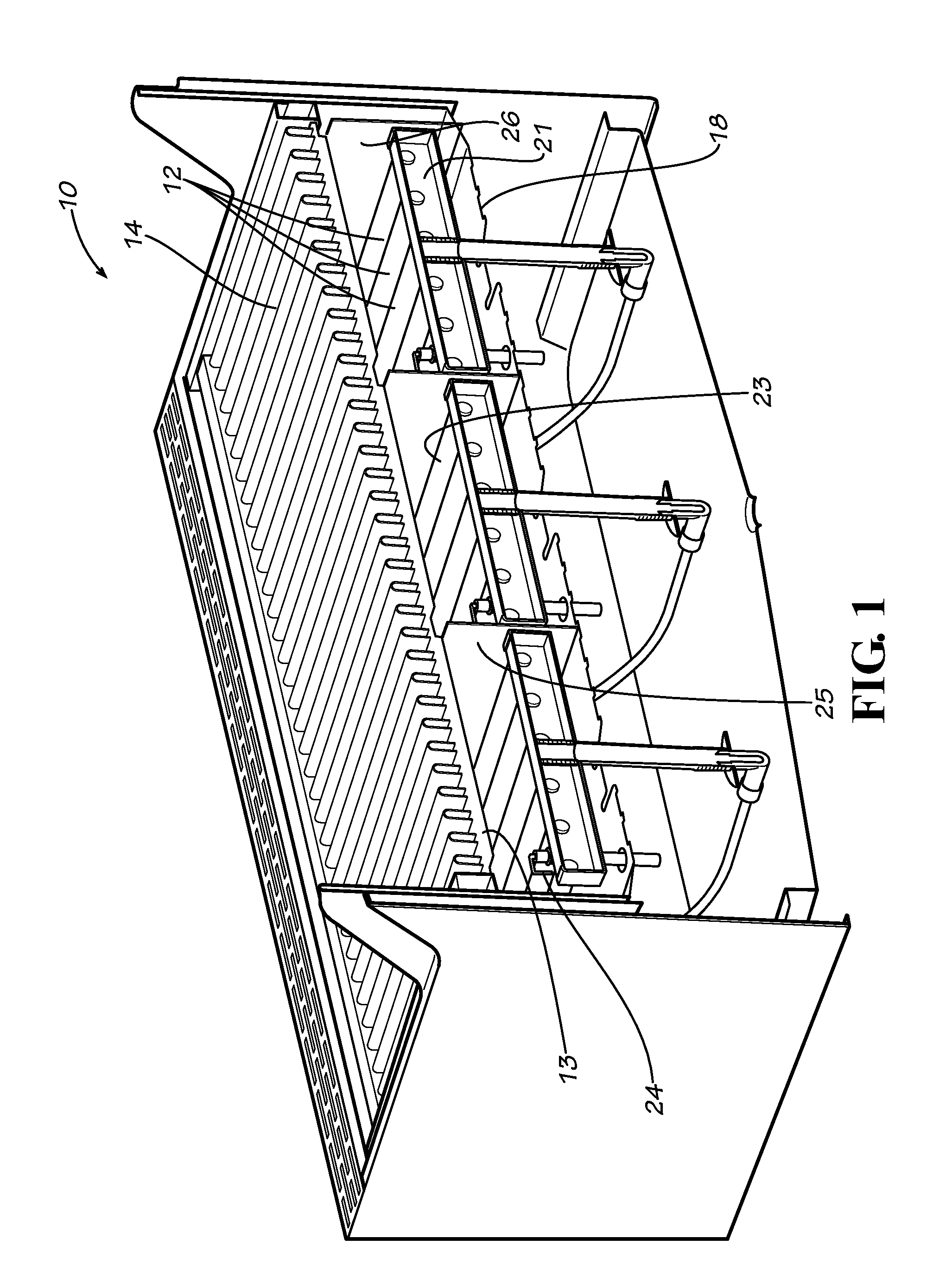
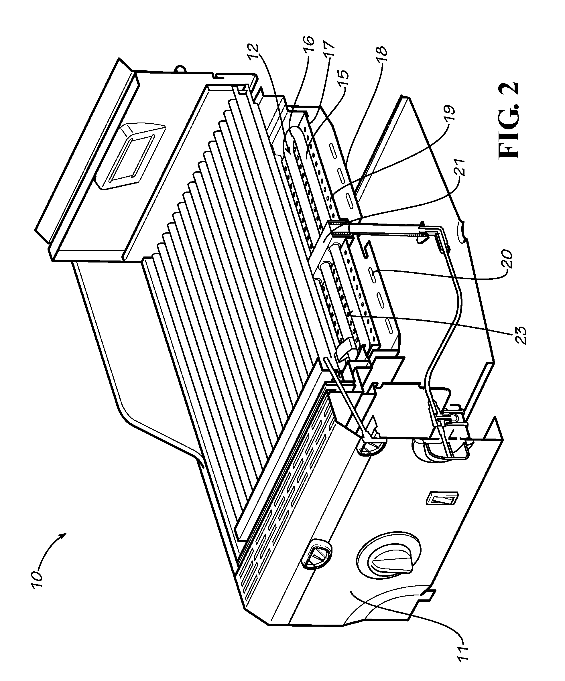
[0005]The present disclosure relates to a burner that can be used under any type of generally horizontal surface to provide infrared emission from that horizontal surface when it is heated by the burner. The present burner provides better heat transfer by vertical impingement of hot gas on the horizontal surface, prevention of pre-ignition by directed cooling using secondary combustion air, and reduced cross sectional area using multiple lower radiation heat shields. Although a horizontal surface will be shown, it should be appreciated that this re-emitting surface could be at some angle up to as high as 15 degrees from the horizontal and still provide the characteristics shown. The present burner is also resistant to extinguishment under windy conditions and has a high gas flow turn down ratio, unlike any construction known in the prior art.

Problems solved by technology

However, radiant infrared burners of known type of construction have various limitations including limited gas flow turn down ratio (defined as the ratio of the maximum gas flow to the minimum possible gas flow), a propensity to extinguish under windy conditions, radiant transfer of heat in a direction downward into the surrounding plenum chamber, high pressure drop across the radiant element, and high cost of fabrication.
Therefore, the inlet gas-air mixture is ready for ignition and so the auto ignition point due to ambient temperature is relatively low which can cause internal fires in the burner.
In addition, radiant burners have surfaces that are at temperatures of 1600 to 1800 degrees F. which are challenging to all types of materials in terms of longevity due to thermal cycles or thermal shock in the case of ceramics or high temperature corrosion in the case of metals.

Method used


Image

  • Parallel tube burner with improved cooling and reduced size
  • Parallel tube burner with improved cooling and reduced size
  • Parallel tube burner with improved cooling and reduced size

Examples


Embodiment Construction

[0014]The present disclosure relates to a burner that is used to heat an infrared emitter, such as might be found in an outdoor gas barbeque grill. While the discussion which ensues will focus on the use of the burner in such an environment, such discussion should not be construed in any way to be limiting or restrictive. The present burner can be used in other types of gas fired appliances, such as stoves, water heaters, furnaces, etc. Reference is now made to the drawings, where like numbers designate like elements.

[0015]The present burner can be used under the plate and grate system that is the subject of U.S. Patent Publication No. 2006 / 00021517 to Best. This application discloses a stove for cooking using an infrared emitting apparatus. Such apparatus is normally heated by the radiant burner shown in U.S. Patent Publication No. 2006 / 0003279. Additional art for heating such an infrared emitting apparatus is taught in U.S. Patent Application 2009 / 0202688 A1 as noted above. Howeve...


PUM


Abstract

A firebox for a gas grill with an infrared re-emitter surface at the top, at least one heat shield at the bottom, and sidewalls intermediate between the heat shields and the emitter plate forming a box like structure in which multiple small cross sectional area tubes with gas burner ports on the top or sides are disposed in an array between the heat shield and the emitter plate. The heat shield below the burner tubes has openings disposed below the burner tubes to admit secondary combustion air and provide cooling of the burner tubes preventing pre-ignition.

Description

CROSS REFERENCE RELATED APPLICATION[0001]This application claims priority to U.S. Provisional Application Ser. No. 61 / 106,352 filed Oct. 17, 2008, which is entirely incorporated herein by reference.BACKGROUND[0002]Outdoor barbeque grills used for cooking food are typically fired with one of three conventional heating systems. The heating systems are typically either charcoal briquettes in a smoldering condition, burners fueled with either natural gas, propane, or a similar fuel, or by means of electrical elements that may be used alone or in conjunction with a heatable radiant material. Over the years, the use of heatable radiant materials has evolved from charcoal briquettes to lava rocks, to ceramic briquettes, plates or blocks. Such a construction is shown by U.S. Pat. No. 3,277,948 or 3,561,902, to Best. Other types of radiant burners use woven ceramic mesh, woven metal wire, and perforated metal plates as described in various patents over the years. However, with the advent of ...

Claims


Application Information

Patent Timeline
IPC IPC(8): A47J37/07F24C3/08
CPCA47J37/0713A47J37/0682
Inventor AHMED, MALLIK R.
Owner CHAR BROIL
Learn More