Sample Inspection Apparatus, Sample Inspection Method and Sample Inspection System

a technology of sample inspection apparatus and sample, which is applied in the direction of instruments, heat measurement, machines/engines, etc., can solve the problems of instrument contamination, sample on the film leakage into the sem instrument during sem imaging and diffuse, and damage to the film due to so as to prevent the contamination of the inside of the instrument, limit the operation of the manipulator, and prevent the effect of film damag

Inactive Publication Date: 2010-04-22
JEOL LTD
View PDF8 Cites 28 Cited by
  • Summary
  • Abstract
  • Description
  • Claims
  • Application Information

AI Technical Summary

Benefits of technology

[0030]Even when the film is destroyed by the manipulator, contamination of the inside of the instrument can be prevented by mounting an open-close valve for partitioning off the space between the film and the primary beam irradiation system.
[0031]In addition, in the present invention, the operation of the manipulator is controlled based on the result of a measurement of the position of the film or on the result of a measurement of an electrical or physical amount between the tip of the manipulator and the film to prevent the tip of the manipulator from touching the film or to limit the operation of the manipulator when the tip is in contact with the film.
[0032]Consequently, the tip of the manipulator can be prevented from touching the film or, if the tip touches the film, application of an unwanted external force to the film by the tip of the manipulator can be prevented. This assures that damage to the film due to operation of the manipulator can be prevented.
[0033]As a result, when the sample on the film is observed or inspected using SEM, it is assured that destruction of the film due to the manipulator is prevented; otherwise, the sample would diffuse, contaminating the apparatus.
[0034]The provision of the open-close valve described above makes it possible to partition off the space between the film and the primary beam irradiation system when or immediately before the tip of the manipulator touches the film. Therefore, if the film should be destroyed, contamination of the apparatus can be prevented.

Problems solved by technology

For example, if the tip of the manipulator touches the film on the sample holder, and if an unwanted external force is applied to the film from the tip of the manipulator, the film will be damaged.
As a result, if the film is destroyed, the sample on the film leaks into the SEM instrument during SEM imaging and diffuses.
Consequently, the instrument is contaminated.

Method used


Image

  • Sample Inspection Apparatus, Sample Inspection Method and Sample Inspection System
  • Sample Inspection Apparatus, Sample Inspection Method and Sample Inspection System
  • Sample Inspection Apparatus, Sample Inspection Method and Sample Inspection System

Examples


embodiment 1

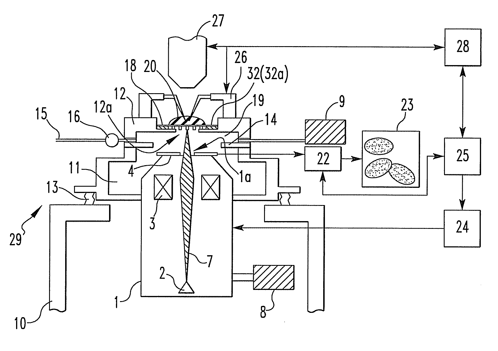
[0043]FIG. 1 is a schematic diagram showing a first embodiment of an inspection apparatus according to the present invention. In the figure, an electron gun 2 forming an electron source is disposed in an electron optical column 1 forming primary beam irradiation system. An electron beam (a kind of charged-particle beam) 7 acting as a primary beam is emitted from the electron gun 2 and accelerated. The beam 7 is focused by a condenser lens (objective lens) 3.

[0044]The electron beam 7 focused in this way is made to hit a sample 20 via a sample-holding film 32. The sample 20 is held on this sample-holding film 32 forming a sample holder 18. At this time, the beam 7 is deflected by deflection system (not shown). As a result, the beam 7 scans the sample 20. The front end of the electron optical column 1 is connected with a vacuum chamber 11. The base end of the electron optical column 1 in which the electron gun 2 is mounted is located below the vacuum chamber 11. The sample 20 is held o...

embodiment 2

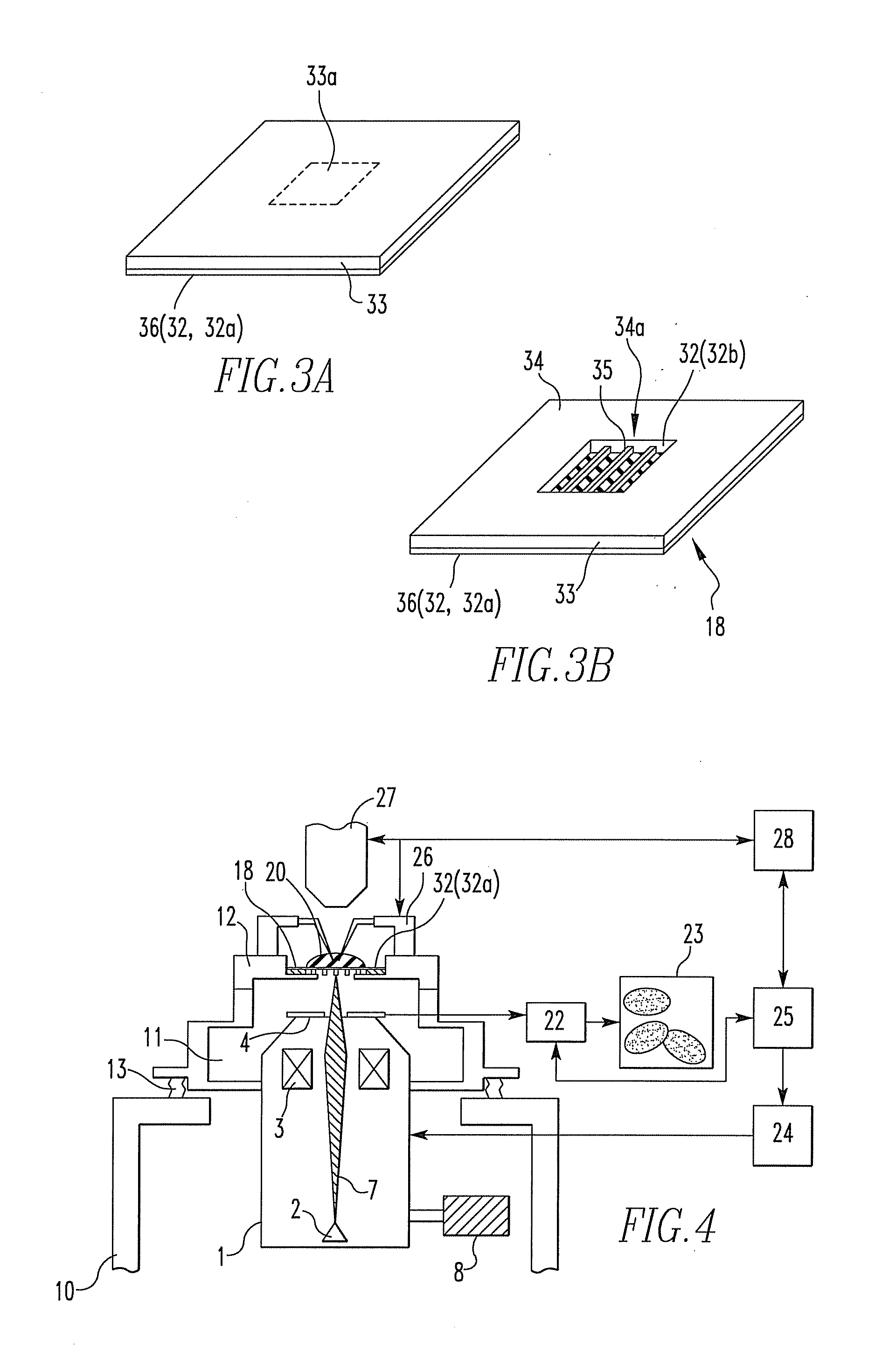
[0116]Where the resistance of the sample-holding film 32 is sufficient, an inspection apparatus (FIG. 4) from which the open-close valve 14 has been omitted can also be used. The structure of the apparatus is simplified. The cost of the apparatus can be reduced. Furthermore, the working distance between the sample and the electron optical column 1 can be reduced. This leads to an improvement of the resolution and to an improvement of the efficiency at which backscattered electrons are detected. Images of higher quality can be captured.

embodiment 3

[0117]As shown in FIG. 5, driver 17 having a bellows structure is mounted between an open-close valve 14 and a sample holder placement portion 12 in a vacuum chamber 11. Consequently, a sample holder 18 and a sample-holding film 32 formed on the holder can move vertically and horizontally independent of an optical microscope 27 and an electron optical column 1. Accordingly, if a region that can be irradiated with an electron beam 7 greatly deviates in position from an observed region of the sample 20, the irradiated region can be made to overlap the observed region by moving the sample holder 18.

[0118]If the optical axis of the optical microscope 27 is aligned with the optical axis of the electron optical column 1 within a tolerance range of less than 50 μm, or if the center of the field of view of the optical microscope 27 (the center of the optical image) is aligned with the center of the field of view of the SEM image (the center of the region irradiated with the electron beam 7)...


PUM

PropertyMeasurementUnit
thicknessaaaaaaaaaa
sizesaaaaaaaaaa
distanceaaaaaaaaaa

Abstract

Sample inspection apparatus, sample inspection method, and sample inspection system are offered which can give a stimulus to a sample held on a film when the sample is inspected by irradiating it with a primary beam (e.g., an electron beam or other charged-particle beam) via the film. The apparatus has the film, a vacuum chamber, primary beam irradiation column, signal detector, and a controller for controlling the operations of the beam irradiation column and signal detector. The sample is held on a first surface of the film opened to permit access to the film. The vacuum chamber reduces the pressure of the ambient in contact with a second surface of the film. The irradiation column irradiates the sample with the primary beam via the film from the second surface side. The detector detects a secondary signal produced from the sample in response to the irradiation.

Description

BACKGROUND OF THE INVENTION[0001]1. Field of the Invention[0002]The present invention relates to a sample inspection apparatus, sample inspection method, and sample inspection system capable of inspecting a sample by irradiating the sample held on a film with a primary beam, such as a charged-particle beam. Especially, the present invention relates to techniques permitting one to observe reactions of a sample consisting of biological cells when a stimulus is given to the cells and to inspect the sample.[0003]2. Description of Related Art[0004]In life science and pharmaceutical applications, it is important that stimuli (such as electricity, chemical substances, and medicines) are given to biological cells and that resulting reactions are observed. In the past, optical microscopes have been used for such observations. Often, important parts to be observed are microscopic regions of less than 0.1 μm, which cannot be observed with optical microscopes.[0005]For example, diseases arising...

Claims


Application Information

Patent Timeline
Patent Type & Authority Applications(United States)
IPC IPC(8): G01N23/225
CPCG01N23/2251H01J37/20H01J37/228H01J37/256H01J2237/2808H01J2237/206H01J2237/208H01J2237/2608H01J37/28
Inventor NISHIYAMA, HIDETOSHI
Owner JEOL LTD
Why Eureka
Try Eureka