
Head gimbal assembly for heat-assisted magnetic recording

Active Publication Date: 2010-04-22
TDK CORPARATION +1
View PDF6 Cites 17 Cited by
  • Summary
  • Abstract
  • Description
  • Claims
  • Application Information

AI Technical Summary

Benefits of technology

[0017]Accordingly, it is an object of the present invention to provide an HGA with a radiation structure that can effectively get away the heat generated from a light source during the operations, and to provide a magnetic recording apparatus having the HGA(s).
[0027]In the above-described HGA according to the present invention, provided as a radiation structure for the light source is: a heat flow path originating from the end surface opposite to the source-installation surface of the light source, and reaching the first pad through the first connection member; a heat flow path originating from the upper surface of the suspension (the first pad), and reaching the lower surface of the suspension (the second pad); a heat flow path originating from the second pad, and reaching the electrode of the head part through the second connection member; and a heat flow path originating from the electrode, and reaching the opposed-to-medium surface. Conclusively, the construction of the heat flow paths allows the heat generated from the light source during operations to be effectively radiated through the opposed-to-medium surface. Therefore, an effective radiation structure can be realized, without depending on the heat radiation simply through the unit substrate or the slider substrate.
[0028]In the HGA according to the present invention, the first pad and the second pad are preferably opposite to each other and are preferably positioned so as to sandwich said suspension. This arrangement can decrease the length of the heat flow path between the first and second pads up to the thickness of the suspension, and the thermal impedance of the heat flow path can be further reduced. Further, at least a portion of the suspension such as a flexure, including a portion to which the heat-assisted magnetic recording head is attached, preferably has a layered structure comprising a substrate and two electrically insulating layers provided so as to sandwich the substrate. The layered structure can form a desired heat flow path, while securing electrical insulation between the light source / the head part and suspension. In this case, the electrically insulating layer preferably includes polyimide resin, silicon carbide or aluminum nitride, or composite material composed of silicon carbide, aluminum nitride or metal, and polyimide resin. Further, the first connection member and the second connection member are preferably made of solder.

Problems solved by technology

However, the decrease in size of the magnetic microparticles raises a problem of degradation of thermal stability of magnetization due to decrease in volume.
A problem to be solved in the HGA for heat-assisted magnetic recording is to construct a radiation structure for effectively getting away the heat generated from a light source to attain a stable light emitting operation of the light source.
Resultantly, it has been very difficult to radiate heat with sufficient quantity even if the p-electrode of the laser diode is stuck to the substrate.
When the heat radiation of the laser diode is not enough, the light-emitting operation becomes unstable, and further, the laser diode itself is sometimes possible to be damaged.
From this viewpoint, in the above-described heat-assisted magnetic recording head, the heat radiation through the ABS has not been enough, because the light source is positioned considerably separated apart from the ABS.

Method used


Image

  • Head gimbal assembly for heat-assisted magnetic recording
  • Head gimbal assembly for heat-assisted magnetic recording
  • Head gimbal assembly for heat-assisted magnetic recording

Examples


Embodiment Construction

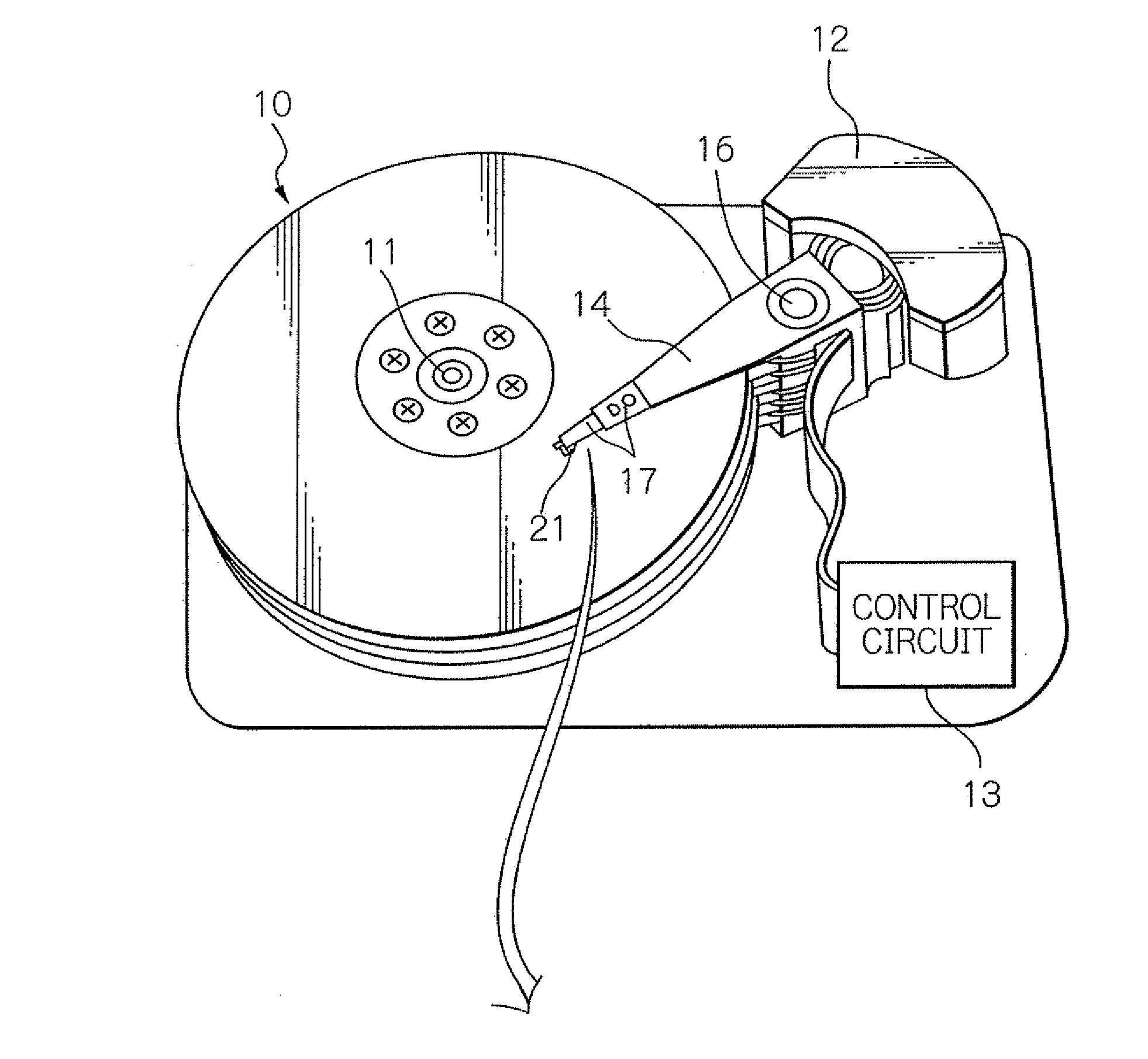
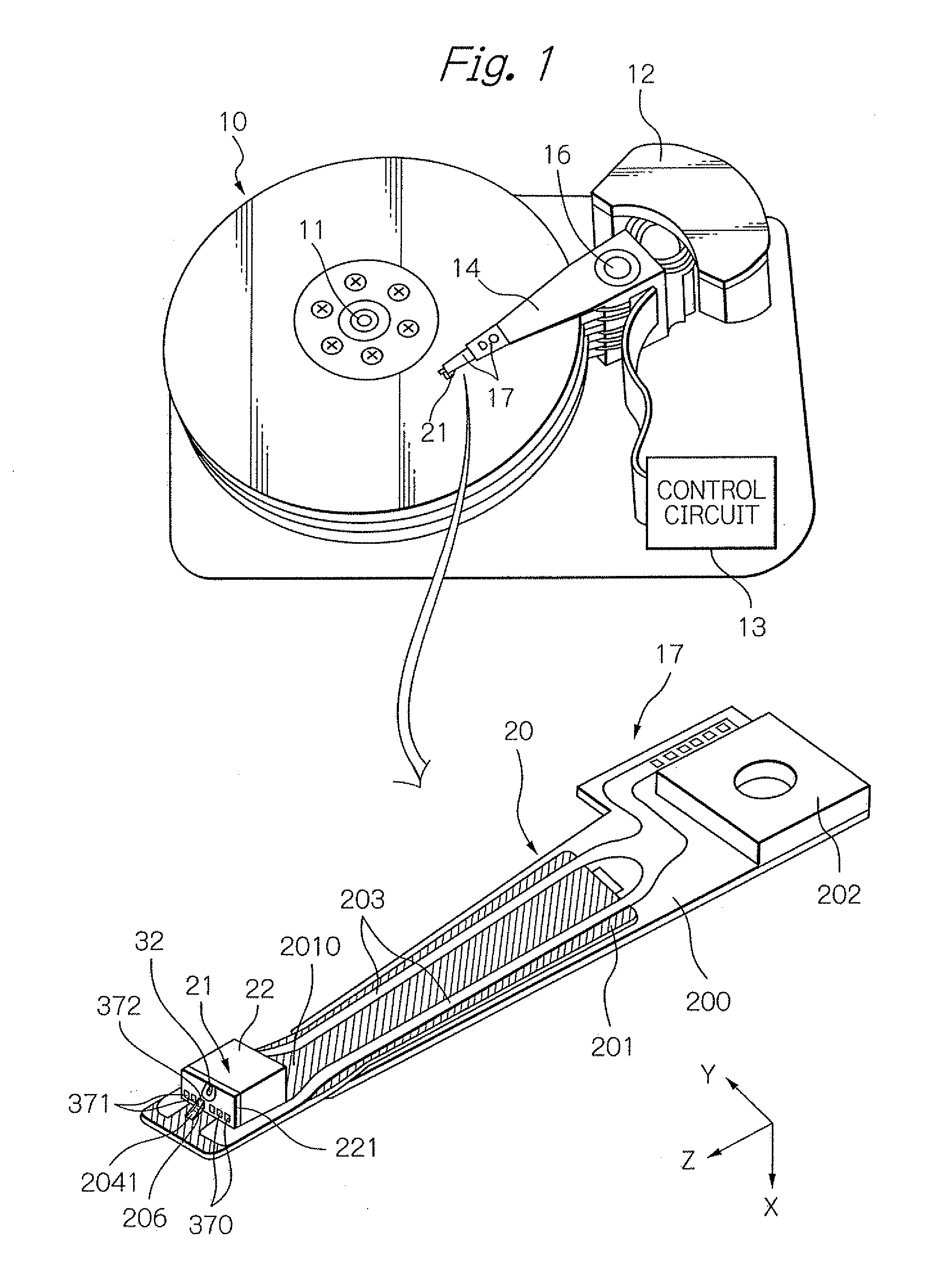
[0039]FIG. 1 shows a perspective view schematically illustrating a structure of a major part in one embodiment of a magnetic recording apparatus and a head gimbal assembly (HGA) according to the present invention. Here, in the perspective view of the HGA, a lower surface 2010 of a suspension 20 of the HGA is presented as the upper side, the surface 2010 facing a magnetic-disk surface.

[0040]A magnetic disk apparatus as a magnetic recording apparatus shown in FIG. 1 includes: a plurality of magnetic disks 10 rotating around a rotational axis of a spindle motor 11; an assembly carriage device 12 provided with a plurality of drive arms 14 thereon; an HGA 17 attached on the top end portion of each drive arm 14 and provided with a heat-assisted magnetic recording head 21; and a recording / reproducing and light-emission control circuit 13 for controlling write / read operations of the heat-assisted magnetic recording head 21 and further for controlling the emission operation of a laser diode ...


PUM


Abstract

Provided is an HGA with a radiation structure that can effectively get away the heat generated from a light source. The HGA comprises a suspension and a head comprising a slider and a light source unit. The suspension comprises an opening, and the light source unit projects through the opening to the opposite side to the slider in relation to the suspension. Further, the first and second pads are provided on the upper and lower surfaces of the suspension, respectively, the end surface opposite to the source-installation surface of the light source is connected to the first pad by the first connection member, and an electrode of the head part is connected to the second pad by the second connection member. Thus, heat flow paths can be provided from the light source to the opposed-to-medium surface to allow effective radiation of the heat generated from the light source.

Description

BACKGROUND OF THE INVENTION[0001]1. Field of the Invention[0002]The present invention relates to a head gimbal assembly provided with a magnetic head for writing data signals according to heat-assisted magnetic recording technique, and to a magnetic recording apparatus provided with the head gimbal assembly.[0003]2. Description of the Related Art[0004]As the recording density of a magnetic recording apparatus, such as a magnetic disk apparatus, becomes higher, further improvement has been required in the performance of a thin-film magnetic head and a magnetic recording medium. As the thin-film magnetic head, a composite-type thin-film magnetic head is widely used, which has a stacked structure of a magnetoresistive (MR) element for reading data and an. electromagnetic transducer for writing data.[0005]On the other hand, the magnetic recording medium is generally a kind of discontinuous body of magnetic microparticles gathered together. Here, one record bit consists of a plurality of...

Claims


Application Information

Patent Timeline
IPC IPC(8): G11B5/48
CPCG11B2005/0021G11B5/4833
Inventor SHIMAZAWA, KOJIMURAKOSHI, RYUTA
Owner TDK CORPARATION
Learn More