Impermeable porous substrate for planar fuel cells and integrated packaging

a technology of impermeable porous substrate and fuel cell, which is applied in the direction of fuel cell, portable application adaption, sustainable building, etc., can solve the problem of relatively unattractive embodiment of said embodiment, and achieve the effect of compact aspect and better power density in w/kg or w/l

Inactive Publication Date: 2010-04-22
COMMISSARIAT A LENERGIE ATOMIQUE ET AUX ENERGIES ALTERNATIVES
View PDF7 Cites 2 Cited by
  • Summary
  • Abstract
  • Description
  • Claims
  • Application Information

AI Technical Summary

Benefits of technology

[0032]To great advantage, the selected material is a polymer that has the characteristic of being thermoplastic, in other words capable of softening under the effect of heat. As a consequence, a rise in the localized and peripheral temperature, applied over the entire accessible surface of the permeable polymer after the layers are stacked, causes a deformation of the material. Said softening enables the channels or the pores of the material to be filled and a dense layer to be obtained. The integrated cell assembly thus has a fuel diffusion area, while being i

Problems solved by technology

Their integration in the fuel cell involves additional cutting and

Method used


Image

  • Impermeable porous substrate for planar fuel cells and integrated packaging
  • Impermeable porous substrate for planar fuel cells and integrated packaging
  • Impermeable porous substrate for planar fuel cells and integrated packaging

Examples


Embodiment Construction

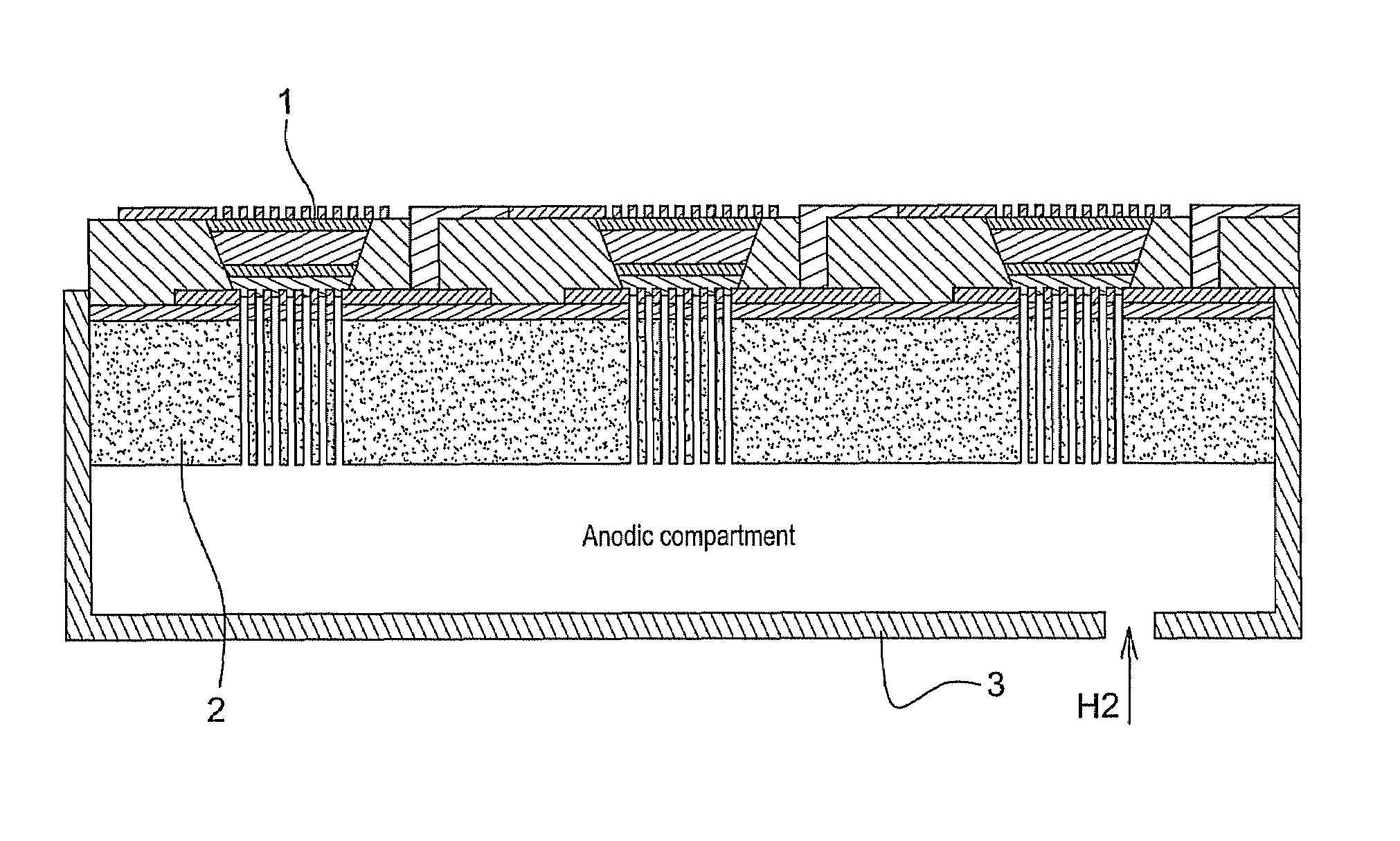
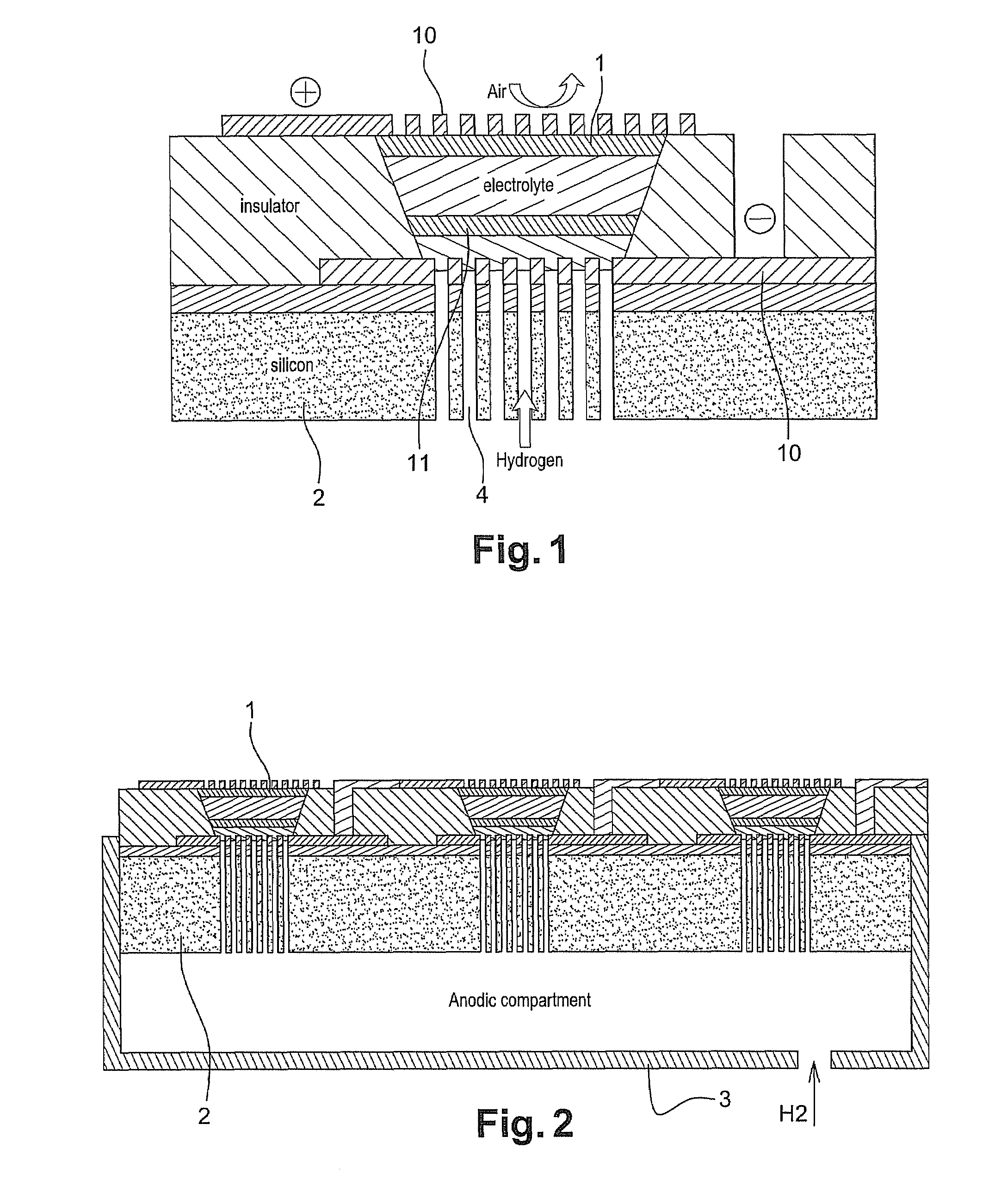
[0050]A polyethylene substrate 2, having 40% porosity with pores of 20 μm, and having a thickness of 1.6 mm is used as a support for stacking the cell core 1.

[0051]As disclosed by the invention, the first step comprises depositing a first layer of gold acting as electronic collector 10. The active anode layer 11 is then deposited by sputtering. Said layer contains a catalyst, in the case in point platinum. It is deposited locally like the gold layer, to form in the end a plurality of cell cores of 1 cm2.

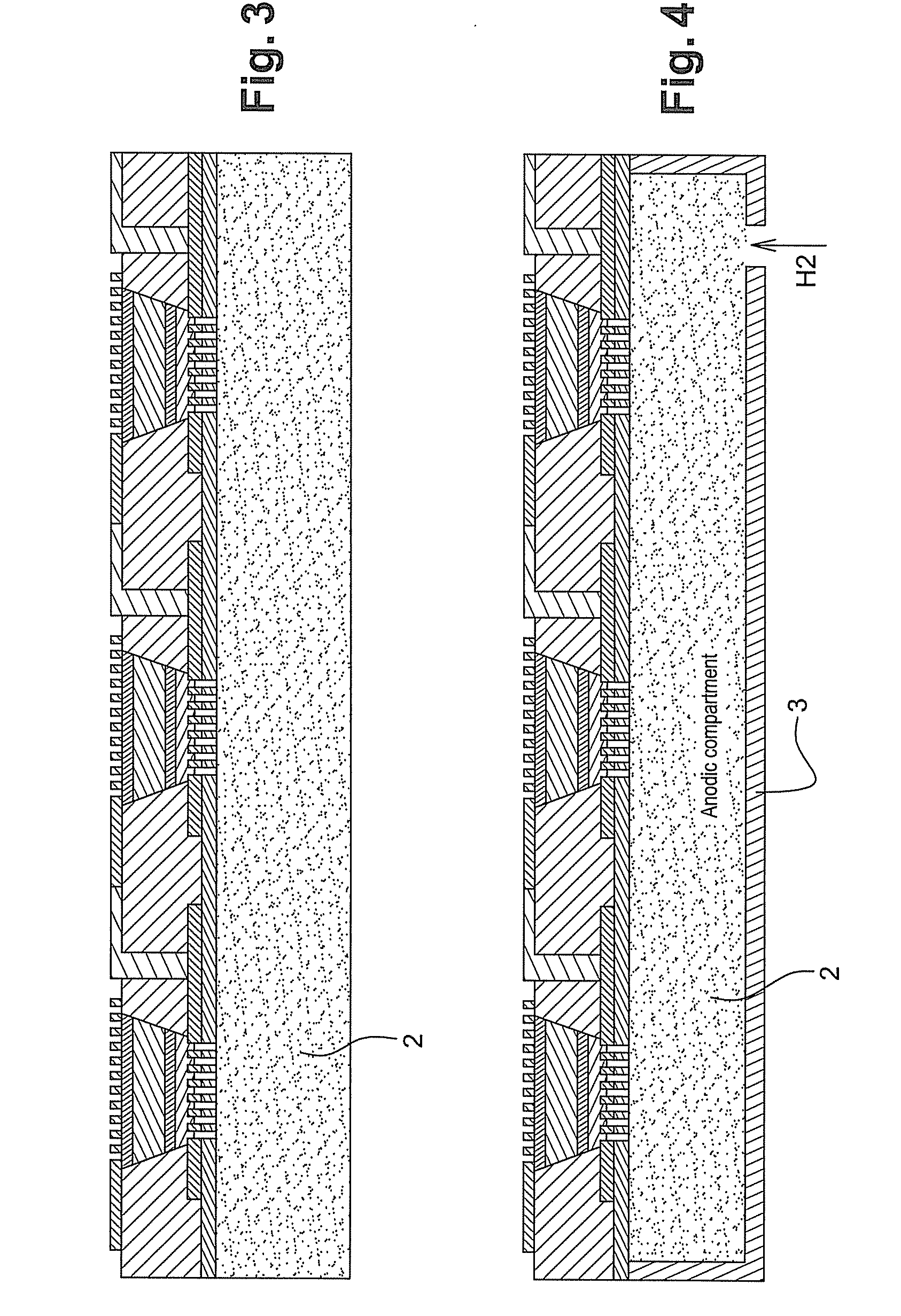
[0052]A solution of Nafion® (trademark Dupont de Nemours), corresponding to a dispersion of sulfonated perfluorinated polymers, is then deposited by coating over the whole surface of the substrate. The active cathode layer 11 is then applied by sputtering, in the same way as the anode layer, also localized opposite the cathode layer (FIG. 3).

[0053]This assembly is then placed in a mould with dimensions appropriate to the size of the substrate 2. The assembly is placed under 1 bar of ...


PUM

PropertyMeasurementUnit
Pore sizeaaaaaaaaaa
Pore sizeaaaaaaaaaa
Thicknessaaaaaaaaaa

Abstract

The present invention relates to a support for a planar fuel cell core, produced using a material permeable to the fuel of the cell, and sealed over at least one of its outer faces.

Description

FIELD OF THE INVENTION[0001]The present invention relates to the field of solid polymer electrolyte fuel cells, and the implementation thereof in generating electrical power from a few hundred milliwatts to a few tens of watts for portable uses.[0002]The invention relates more specifically to a method of developing the cell core in planar fuel cells, and is based on the use of a sealed porous substrate.[0003]Said invention relates to hydrogen fuel cells, but also to fuel cells involving liquids, such as methanol, ethanol, formic acid, ethylene glycol or solutions of sodium borohydride. It also relates to anionic or cationic electrolyte fuel cells.BACKGROUND OF THE INVENTION[0004]There are on the whole two types of architecture for fuel cells:[0005]filter press architecture comprises stacking a plurality of fuel cell cores. Said first architecture is generally preferred where high-power uses are involved.[0006]alternatively, planar architecture comprises juxtaposing a plurality of fu...

Claims


Application Information

Patent Timeline
IPC IPC(8): H01M8/10H01M2/10
CPCH01M8/0271H01M8/0284H01M8/0286H01M8/1011H01M8/1097Y10T29/4911H01M2008/1095H01M2250/30Y02E60/523Y02B90/18H01M8/241H01M8/2418Y02B90/10Y02E60/50H01M8/026H01M8/242
Inventor CAPRON, PHILIPPEROUGEAUX, ISABELLEDELMAS, JEROMEMARTINENT, AUDREY
Owner COMMISSARIAT A LENERGIE ATOMIQUE ET AUX ENERGIES ALTERNATIVES
Why Eureka
Try Eureka