Spark plug and internal combustion engine provided with the same

a technology of spark plug and internal combustion engine, which is applied in the direction of spark plug, machine/engine, mechanical apparatus, etc., can solve the problems of unlikely to obtain the cooling effect of the insulator, the spark is unlikely to be exposed to the air-fuel mixture, and the anti-pre-ignition performance tends to deteriorate, so as to prolong the length of the ground electrode, improve the ignitability, and ensure the effect of ignitability

Inactive Publication Date: 2010-04-29
NGK SPARK PLUG CO LTD
View PDF24 Cites 2 Cited by
  • Summary
  • Abstract
  • Description
  • Claims
  • Application Information

AI Technical Summary

Benefits of technology

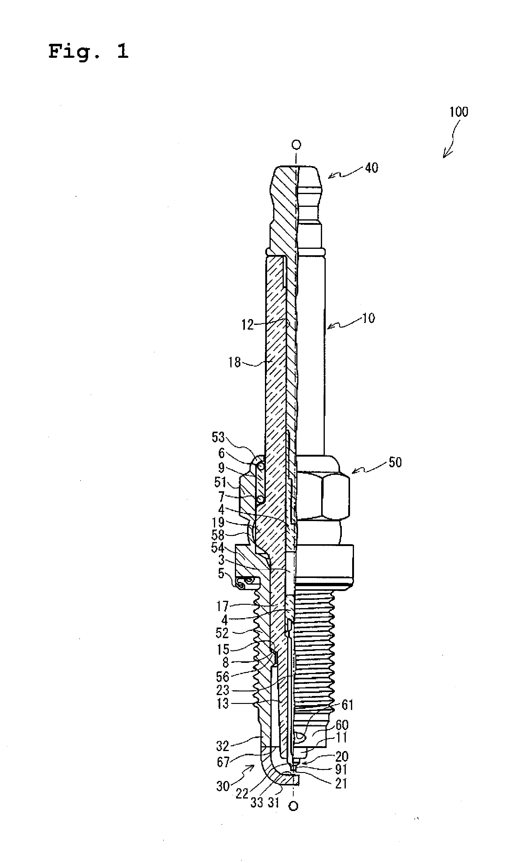
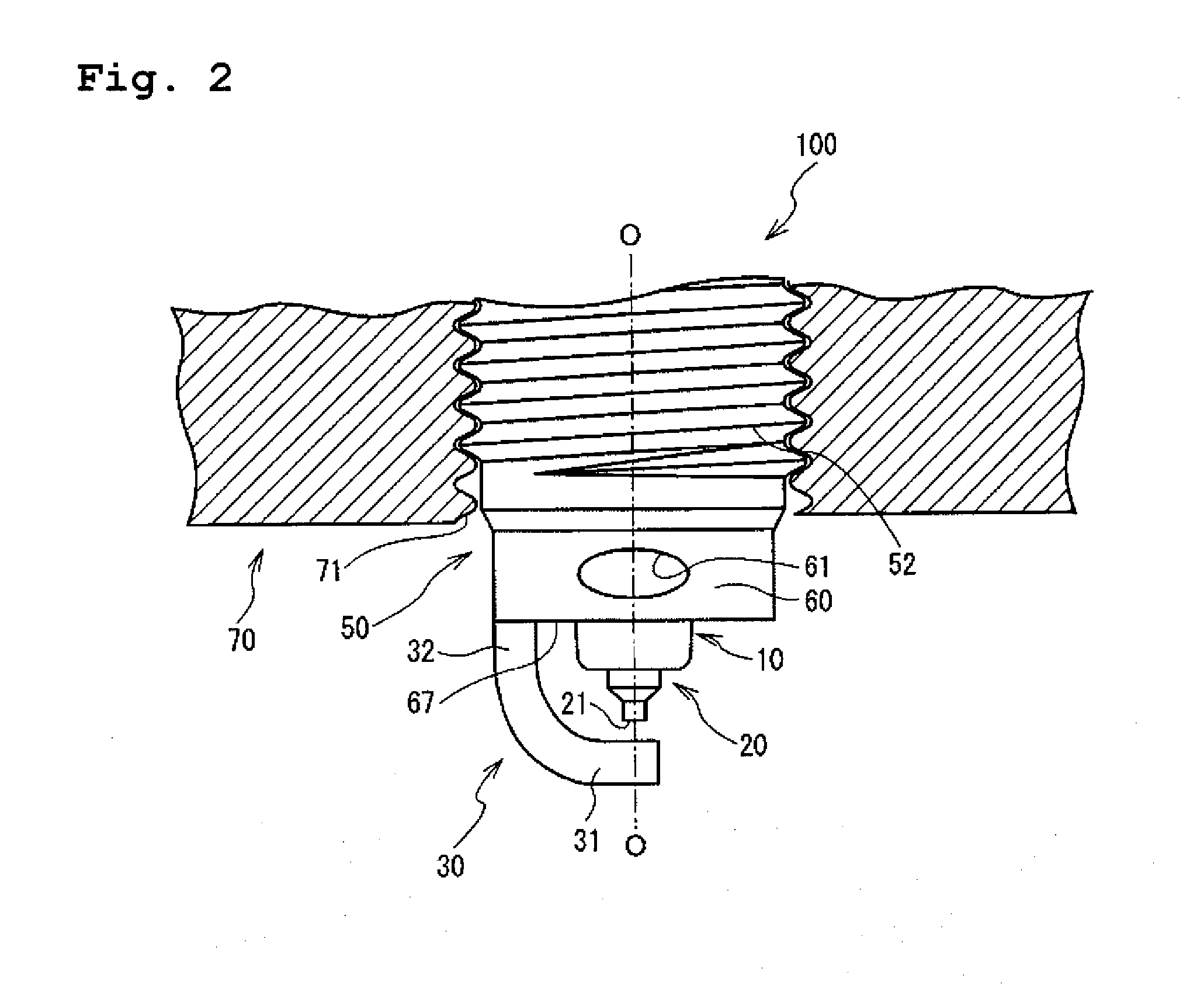
[0007]According to one aspect of the present invention, a spark plug, comprising: a center electrode; an insulator having therein an axial bore that extends in an axis direction of the center electrode to accommodate the center electrode in the axial bore; a metal shell surrounding and holding the insulator in a radial direction said metal shell being mountable on a mounting portion of an internal combustion engine; a cylinder-shaped cylindrical portion formed in a front end portion of the metal shell and projecting on the front end side with respect to the mounting portion when the metal shell is mounted on the mounting portion; and a ground electrode in which one end thereof is joined to a front end of the cylindrical portion, and the other end thereof opposes one end of the center electrode to form a spark discharge gap with a front end portion of the center electrode, wherein the cylindrical portion includes one or more ventilating portions which communicates with an inside and an outside of the cylindrical portion and which is comprised of a notch.
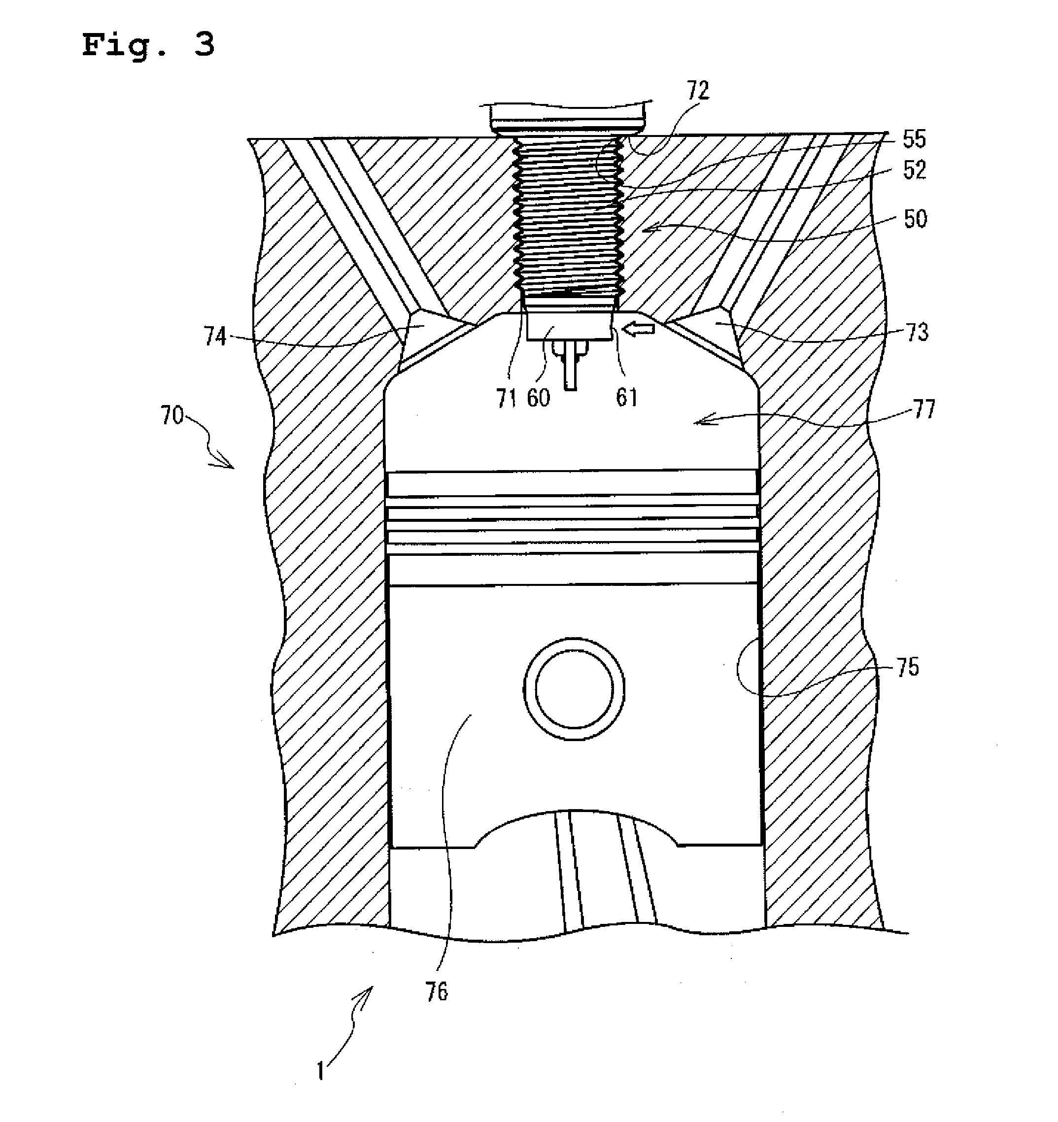
[0008]In accordance with a first aspect of the present invention, there is provided a spark plug wherein the cylinder-shaped cylindrical portion is formed in the front end portion of the metal shell and projects on the front end side with respect to an inner face of the internal combustion engine, and the ventilating portion is comprised of a notch formed in the cylindrical portion. The ground electrode is joined to the front end of the cylindrical portion so that the spark discharge gap projects into the combustion chamber, thereby improving the ignitability. Further, when the spark discharge gap projects into the combustion chamber, it is not necessary to extend the length of the ground electrode. Thus, thermal conductivity of the ground electrode and the endurance over vibration or the like does not deteriorate. Furthermore, forming the ventilating portion in the cylindrical portion establishes a path for the air-fuel mixture flowing near the insulator through the ventilating portion, and the cooling effect on the insulator, which is produced by the flowing of the air-fuel mixture, can be obtained.
[0009]Moreover, forming the ventilating portion, a new edge (dihedral angle portion) is formed in the cylindrical portion. Since the field intensity near the edge becomes greater than that in a portion where no edge is formed, the spark discharge through the edge portion can be produced even when the spark discharge (side sparks or flashover) occurs inside of the metal shell due to a fouling of spark plug. In this situation, it is possible to remove the carbon adhering to the surface of the insulator, thereby preventing the fouling of the spark plug. Further, a reduction in the number of flashover occurrences can be achieved. When the spark discharge occurs through the edge portion, the sparks are exposed to and ignites the air-fuel mixture which flows into the cylindrical portion through the ventilating portion. Thus, a flame can be smoothly propagated into the combustion chamber through the ventilating portion. As a result, the air-fuel mixture can be stably combusted.
[0010]In accordance with a second aspect of the present invention, there is provided a spark plug wherein, in a first section including a front end portion of the cylindrical portion of the spark plug according to the first aspect and perpendicular to the axis direction, a length “W” tying both ends of the notch is preferably 0.7 L or more, where a diameter of the insulator in the first section is referred to as “L”.
[0011]The ignition timing at which the pre-ignition occurs is substantially improved when a ratio W / L of the length W tying the both ends of the notch to the diameter L of the insulator is between 0.5 and 0.7. That is, when the ratio W / L is 0.7 or more, an effect of delaying the ignition timing of occurrence of the pre-ignition increases. Thus, when the length W is 0.7 or more as in the spark plug according to the second aspect of the present invention, the size of the notch is sufficient enough to improve the cooling effect. As a result, a further stable combustion of the air-fuel mixture can be achieved.
[0012]In accordance with a third aspect of the present invention, there is provided a spark plug wherein, the first section of the spark plug includes the front end portion of the cylindrical portion of the spark plug according to the first or second aspect and is perpendicular to the axis direction, the sum each of the angles formed between straight lines which connect each end of the notch to a center of the cylindrical portion, respectively, is preferably smaller than the sum each of the angles formed between straight lines which connect each end of the cylindrical portion to the center of cylindrical portion, respectively.

Problems solved by technology

As a result, a cooling effect on the insulator is unlikely to be obtained, and an anti-pre-ignition performance tends to deteriorate.
Further, when a side spark or a flashover occurs between a surface of the insulator and an inner circumferential face of the metal shell due to a fouling of the spark plug, the sparks are unlikely to be exposed to the air-fuel mixture.
Thus, ignitability of the spark plug deteriorates.

Method used


Image

  • Spark plug and internal combustion engine provided with the same
  • Spark plug and internal combustion engine provided with the same
  • Spark plug and internal combustion engine provided with the same

Examples


first embodiment

[0058]First, as an evaluation test 1, a test on a relation between the presence / absence of the ventilating portion 61, 261 and an occurring timing of the pre-ignition was conducted. In the evaluation test 1, three spark plugs A, B and C each having different shape of the cylindrical portion that was provided in the front end portion of the metal shell were prepared. Spark plug A had no ventilating portion in the cylindrical portion. Spark plug B had an oval-shaped through hole in the cylindrical portion which is similar to the spark plug 100 according to the first embodiment. Spark plug C had a U-shaped notch in the cylindrical portion which is similar to the spark plug 200 according to the second embodiment. Then, each spark plug was mounted on the engine head of an internal combustion engine The engine was operated in a full-throttle state at 5600 rpm of engine speed, and the ignition timing was gradually advanced to cause the pre-ignition. Then, an ignition timing where the earli...

second embodiment

[0060]Next, as an evaluation test 2, a test on a relation between the presence / absence of the ventilating portion 261 and a combustion stability was conducted. In the evaluation test 2, the same spark plugs A and C as the first embodiment were prepared. Each spark plug was mounted on the engine head of the internal combustion engine for the test. The internal combustion engine was operated at different fuel injection timing and ignition timing. The combustion stability was then examined as to whether or not any misfiring occurred. The result is shown in FIG. 5. In FIG. 5, both the ignition timing and the fuel injection timing are represented as an angle before top-dead center (BTDC) of a crank. An area shaded with lines shows the stable combustion area of spark plug A, and an area shaded with dots shows the stable combustion of spark plug C. In FIG. 5, as the angle BTDC of the crank shown on a horizontal axis became smaller, the fuel injection timing was late. Further, as the angle ...

third embodiment

[0062]Next, as an evaluation test 3, a test on a relation between a ratio W / L (%) of a notch width W to a diameter L of the insulator in a first virtual section and the occurrence timing of the pre-ignition was conducted. Here, the first virtual section, the diameter L of the insulator in the first virtual section and the notch width W will be described using the spark plug 200 in FIG. 4 as an example. In FIG. 4, the first virtual section S is a cross section that is perpendicular to the axis O direction, and that includes the front end portion of the cylindrical portion. In FIG. 4, the diameter of the insulator 10 in the first virtual section S is shown as “L”, and a length tying both ends of the ventilating portion 261 (notch) in the first virtual section S is shown as “W”. In the evaluation test 3, “W” and “L” were defined as mentioned above, and six spark plugs each having a different ratio W / L (%) were prepared. More particularly, the similar test as the evaluation test 1 was c...


PUM


Abstract

A spark plug comprising a cylindrical portion which projects into a combustion chamber from an inner wall face of an engine head when the spark plug is fixed to the engine head, wherein the cylindrical portion has one or more ventilating portion comprised of a through hole or a notch in an outer circumferential face thereof. An igniting portion projecting into the combustion chamber improves ignitability. Further, because an air-fuel mixture fed from an inlet of the internal combustion engine flows to inside of the cylindrical portion through the ventilating portion, heat of an insulator is taken away and cooled down, whereby an occurrence of pre-ignition is prevented.

Description

FIELD OF THE INVENTION[0001]The present invention relates to a spark plug to be mounted on an internal combustion engine so as to ignite an air-fuel mixture, and to an internal combustion engine provided with the spark plug.BACKGROUND OF THE INVENTION[0002]A spark plug is used for ignition for an internal combustion engine. A conventional spark plug is comprised of: a center electrode; an insulator having an axial bore for receiving the center electrode therein; and a metal shell surrounding and holding the insulator in a radial direction thereof. One end of a ground electrode is joined to the metal shell and the other end of the ground electrode forms a spark discharge gap with a front end portion of the center electrode. The spark discharge gap serves as a firing portion, and an air-fuel mixture is ignited by spark discharge.[0003]When a firing portion of the spark plug is formed so as to project into a combustion chamber, the firing portion is kept as far away from an inner wall ...

Claims


Application Information

Patent Timeline
Patent Type & Authority Applications(United States)
IPC IPC(8): H01T13/08H01T13/20
CPCH01T13/16H01T13/32H01T13/20
Inventor MORI, KIYOTERU
Owner NGK SPARK PLUG CO LTD
Why Eureka
Try Eureka