Optical structure and solar cell using the same

a solar cell and optical structure technology, applied in the field of optical structure and solar cell using the same, can solve the problems of inability to accurately concentrate light rays of different wavelengths in the same area, and the collection of light rays of different wavelengths, so as to improve the photoelectric conversion efficiency of the solar cell and reduce the operating temperature , the effect of accurately concentrating light rays

Inactive Publication Date: 2010-04-29
HOKUANG OPTICS
View PDF3 Cites 3 Cited by
  • Summary
  • Abstract
  • Description
  • Claims
  • Application Information

AI Technical Summary

Benefits of technology

[0010]Another objective of the present invention is to provide an optical structure that implements a plurality of focal points to distribute light over a photoelectric conversion module so as to maintain a solar cell using the optical structure at a relatively low operating temperature and improve photoelectric conversion efficiency of the solar cell.
[0011]The previously mentioned conventional photovoltaic concentrator system needs a conventional primary lens for collecting sunlight. However, the conventional primary lens fails to accurately concentrate light rays of different wavelengths in the same area but presents a variable concentration region in answering to the light rays with different wavelengths. Hence, the present invention is aimed at improving the conventional primary lens for a solar photovoltaic system so as to enable the improved optical structure to concentrate light rays with different wavelengths in a certain operational region. Besides, the present invention equalizes concentration areas of light rays with different wavelengths so as to allow full use of the light rays, thereby enhancing light uniformity and luminance, and significantly improving efficiency of the solar cell. The optical structure of the present invention can be easily applied to the conventional primary lens and thus is economically beneficial.
[0012]According to a known principle of optics, the smaller the included angle between the direction in which light rays with different wavelengths travel and the normal vector of a solar cell, the closer the locations where the light rays enter the solar cell. Given the aforementioned principle, the present invention appropriately divides an existing primary lens as needed, so as to limit boundaries of concentration areas of light rays with different wavelengths to a certain range. Thus, when ranges required by plural identical primary optical operational regions are all limited, light rays with different wavelengths can be collected in a limited range. From another respect, the present invention features limiting light rays in a certain area where the light rays overlap, thereby improving photoelectric conversion efficiency of the solar cell reasonably.
[0013]In view of this, the present invention involves appropriately dividing a primary lens and determining required optical operational regions. Therein, a plurality of said optical operational regions are linked up in an annular array based at the same location so as to construct a complete optical structure. By the improved optical structure, the present invention facilitates improving uniformity throughout the operational regions and increasing the number of focal points, thereby lowering operating temperature, improving photoelectric conversion efficiency, maximizing the service life of the solar cell, and reducing the operational distance between the primary lens and the solar cell.

Problems solved by technology

However, the conventional primary lens fails to accurately concentrate light rays of different wavelengths in the same area but presents a variable concentration region in answering to the light rays with different wavelengths.
Thus, when ranges required by plural identical primary optical operational regions are all limited, light rays with different wavelengths can be collected in a limited range.

Method used


Image

  • Optical structure and solar cell using the same
  • Optical structure and solar cell using the same
  • Optical structure and solar cell using the same

Examples


Embodiment Construction

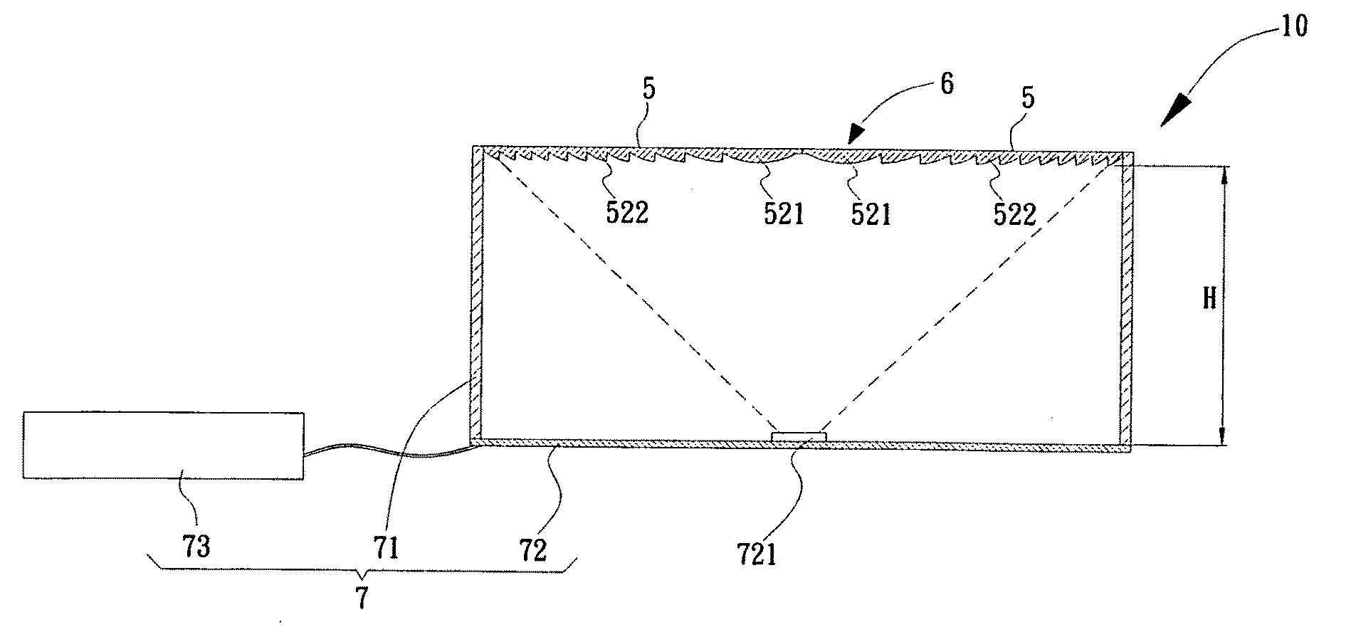
[0028]The present invention is characterized by dividing a typical primary lens 2 into several optical operational regions. To define each said optical operational region, divisional benchmarks are determined taking similar light-entering ranges of light wavelengths. Besides, a divisional angle is determined according to a shape of a concentration region, wherein the angle is derived from dividing 360 degrees by N, where N denotes the number of sides of the polygonal concentration region. Furthermore, the area of the intended concentration region is controlled by a distance between the concentration region and the benchmarks. Afterward, a tip of the optical operational region is taken as a center of rotation so as to form an annular array filling the 360-degree area. Hence, N-1 said regions are integrated into a whole optical structure, thereby accomplishing the present invention.

[0029]Please refer to FIG. 3A. Therein, a triangular optical operational region 5 is defined on a typica...


PUM


Abstract

An optical structure is characterized by improving a primary lens of a photovoltaic concentrator system. The optical structure is accomplished by properly dividing the primary lens, determining required optical operational regions, and arranging the optical operational regions basing on an identical location into an annular array, thereby forming the complete optical structure. The optical structure facilitates enhancing uniformity of light distribution throughout the optical operational regions, improving photoelectric conversion efficiency of a solar cell having the optical structure, and reducing operational distance between the primary lens and the solar cell.

Description

BACKGROUND OF INVENTION[0001]1. Field of the Invention The present invention relates to an optical structure applicable to a concentrator system in a solar cell.[0002]2. Description of the Prior Art[0003]In recent years, due to increasing energy costs and global warming issues, requests for renewable energy bringing less contamination have attracted extensive attention. Especially, solar photovoltaic systems relying on the unfailing solar energy have been developed with various materials and techniques in a worldwide scale for pursuing maximized photoelectric conversion efficiency and reduced power generation costs. Typically, a photovoltaic concentrator system comprises a condensing lens and a high-efficiency solar cell, thereby providing excellent power-generation efficiency with reduced costs of land use per unit area. Besides, such solar photovoltaic systems are not only superior to the traditional thermal power generation solutions in economy but also free from concerns related...

Claims


Application Information

Patent Timeline
Patent Type & Authority Applications(United States)
IPC IPC(8): H01L31/0236H01L31/0232H01L31/04G02B27/12
CPCF24J2/085H01L31/0543Y02E10/52G02B3/08F24S23/31
Inventor CHEN, JAIN-CHENGWU, CHUNG-YINGTSAI, HSIUNG-YUYEH, WEN-CHUNHSU, CHEN-HSIANGHSIAO, TIMCHIEN, SHIH-CHI
Owner HOKUANG OPTICS
Why Eureka
Try Eureka