Flue gas cooling and cleaning system

a technology of flue gas and cleaning system, which is applied in the direction of waste heat treatment, stationary tubular conduit assembly, lighting and heating apparatus, etc., to achieve the effect of improving the efficiency of hydrogen fluoride recovery, reducing harmful emissions, and improving the adsorption efficiency of scrubbing media

Active Publication Date: 2010-04-29
REEL ALESA AG
View PDF2 Cites 20 Cited by
  • Summary
  • Abstract
  • Description
  • Claims
  • Application Information

AI Technical Summary

Benefits of technology

[0026]Cooling of the flue gas before it enters the flue gas cleaning plant is advantageous because the flue gas exiting the reduction cells is at temperatures that exceed the capabilities of the dry scrubbing plant. To achieve the required cooling of the flue gas, we utilise a coolant jacket around the cooling tubes of the flue gas cooler as part of a closed circuit coolant circulation system that couples the flue gas cooler to a heat exchange arrangement that extracts heat energy from the coolant and rejects it to the environment and/or passes it to further plant. Preferably, the closed circuit coolant circulation system flows the coolant through the coolant jacket in a direction counter to the flow of flue gas through the cooling tubes. It is convenient if the

Problems solved by technology

In the absence of such preventative measures, turbulent flow would cause impact of

Method used


Image

  • Flue gas cooling and cleaning system
  • Flue gas cooling and cleaning system
  • Flue gas cooling and cleaning system

Examples


example 1

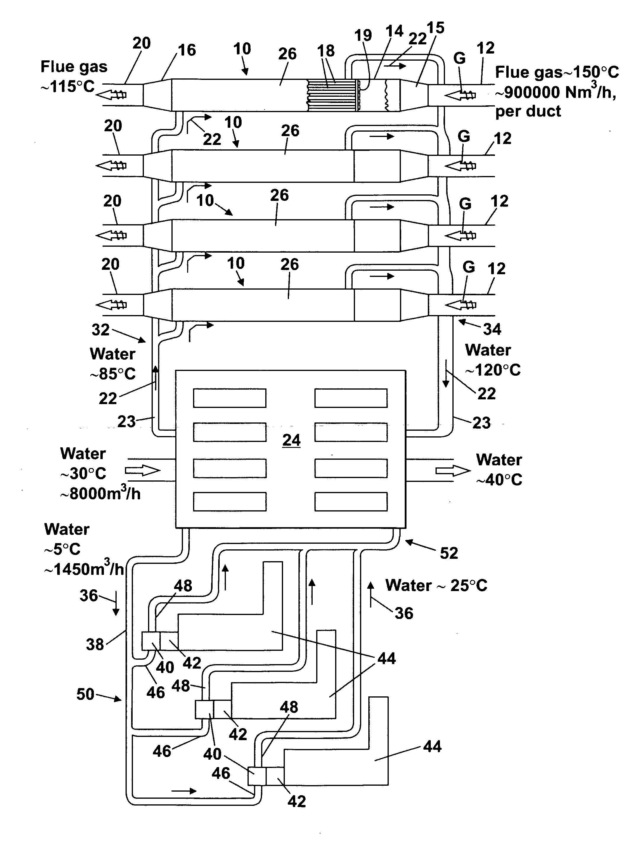
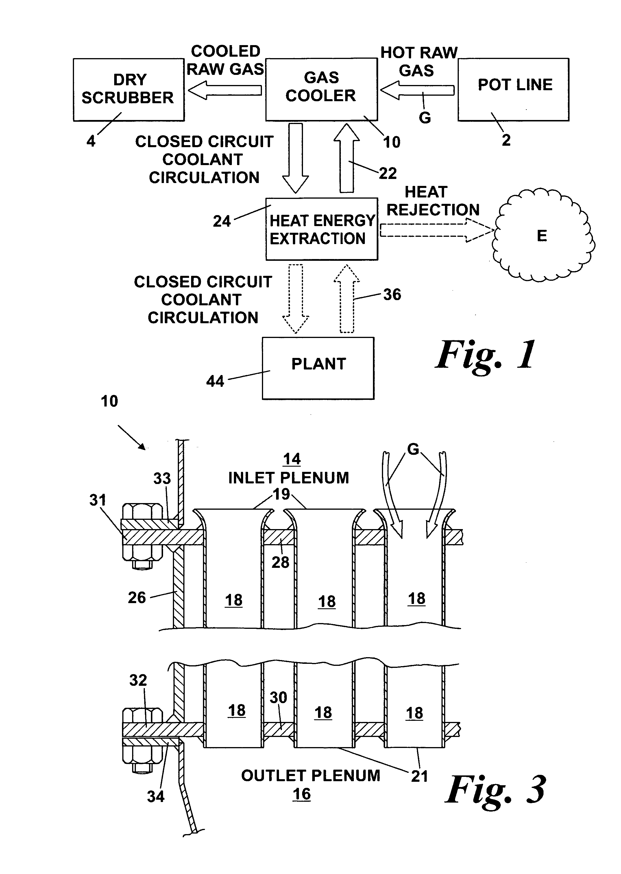
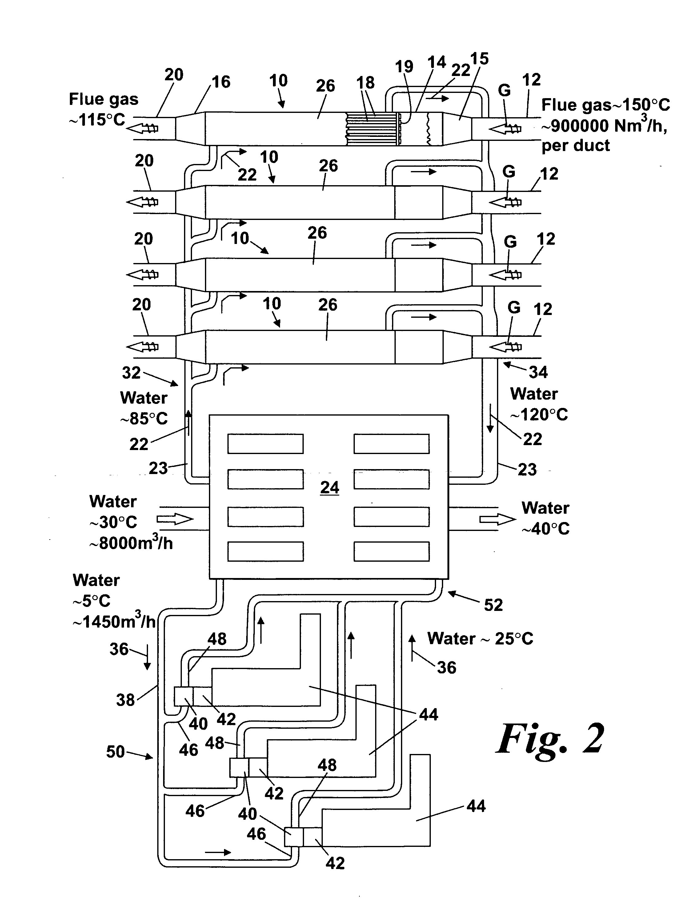
[0061]As previously mentioned, new aluminium smelters tend to be built in tropical or sub-tropical areas of the world. In these areas, electric energy for the reduction cells is produced in gas fired power stations by power blocks comprising gas turbines driving generators. A typical gas turbine used in such a situation is the ALSTOM® GT13 E2M, of 180 MW gross power output, operating on a simple cycle.

[0062]A limiting factor for the efficiency and power output of simple cycle gas turbines is the inlet air temperature to the compressor. In tropical areas, they are designed for a compressor air inlet temperature of +35° C. The energy output of a typical simple cycle power block (gas turbine only) can be increased by more than 10% if the compressor inlet air temperature is reduced from 35° C. to 15° C. The above-described gas cooler facilitates provision of such inlet air cooling to power blocks, in that heat recovered from the flue gas by the gas tube heat exchanger can be used as the...

example 2

[0070]Heat extracted from the flue gas by the gas coolers 10 is used to boost the efficiency of a combined cycle power plant by pre-heating boiler water for the steam-raising part of the combined cycle.

example 3

[0071]Heat extracted from the flue gas by the gas coolers 10 is used to pre-heat water to be desalinated in a desalination plant.


PUM

PropertyMeasurementUnit
Temperatureaaaaaaaaaa
Velocityaaaaaaaaaa

Abstract

An improved flue gas cooler (10), or bank of coolers (10), handles flue gas G from aluminium reduction cells in an aluminium smelter plant. The or each flue gas cooler (10) has a gas inlet chamber (14), a gas outlet chamber (16), and a matrix of gas cooling tubes (18) extending between the inlet chamber and the outlet chamber. Each cooling tube (18) has a bell-shaped inlet end (19) comprising an aerodynamically curved gas-accelerating profile effective to facilitate streamlined flow of flue gas G into the tube. The improved flue gas cooler makes it possible to connect the flue gas cooler to receive hot raw flue gas G direct from the aluminium reduction cells without getting clogged by dust and sublimates present in the flue gas. Once cooled, the flue gas can be safely passed on to a flue gas cleaning plant of the dry scrubbing type. The improved flue gas coolers are advantageously part of a system for using heat energy from the flue gas, in which a closed circuit coolant circulation system circulates coolant through the flue gas cooler and a heat exchange arrangement (24). Heat energy extracted from the coolant by the heat exchange arrangement (24) may be used to increase the efficiency of further plant coupled to the heat exchange arrangement.

Description

FIELD OF THE INVENTION[0001]The present invention relates to an improved gas cooler for cooling flue gas from aluminium smelters. It further relates to an improved flue gas cooling and cleaning system for an aluminium smelter plant, and a system for extracting heat energy from the flue gas.BACKGROUND OF THE INVENTION[0002]Aluminium smelters, comprising many aluminium reduction cells (colloquially called “pots”), produce large amounts of hot flue gas containing hydrogen fluoride, other gases, particulates, and sublimates. For example, an aluminium smelter producing 300,000 tonnes / year of aluminium metal will comprise about 400 reduction cells, arranged in four rows. Such a potline will produce about 3,600,000 Normal cubic metres per hour (Nm3 / h) of flue gas. The raw flue gas must be cleaned, and a well-known type of gas cleaning process used in this connection is the so-called “dry scrubbing” process. Gas cleaning plant using this process is available, for example, from ALSTOM Power ...

Claims


Application Information

Patent Timeline
IPC IPC(8): F28D7/10F28D15/00F27D17/00F28F1/02
CPCC22B7/02C22B21/0038C25C3/22F28F9/182F28D7/16F28F1/025F27D17/004Y02P10/20Y02P10/25
Inventor WEDDE, GEIRBOCKMAN, OLE K.
Owner REEL ALESA AG
Why Eureka
Try Eureka