Surface acoustic wave resonator, surface acoustic wave oscillator, and surface acoustic wave module device
- Summary
- Abstract
- Description
- Claims
- Application Information
AI Technical Summary
Benefits of technology
Problems solved by technology
Method used
Image
Examples
first embodiment
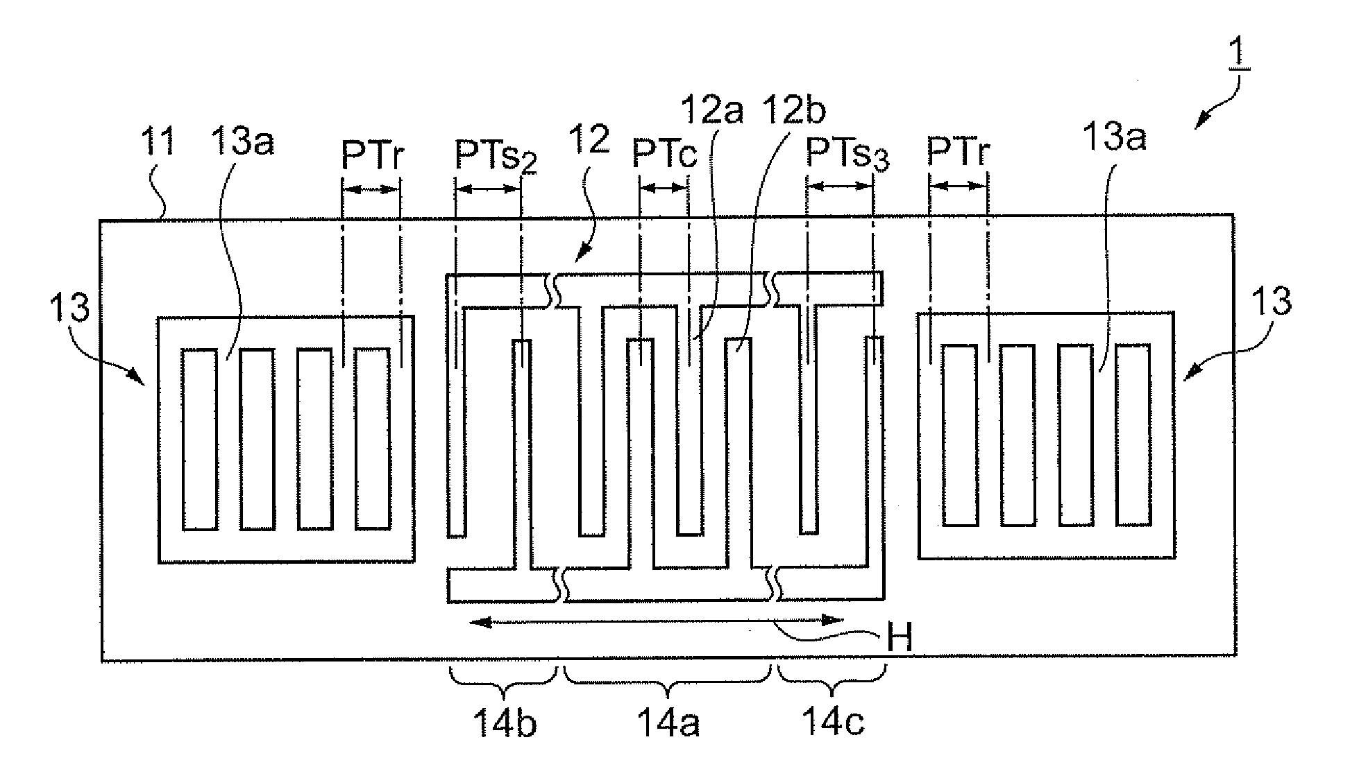
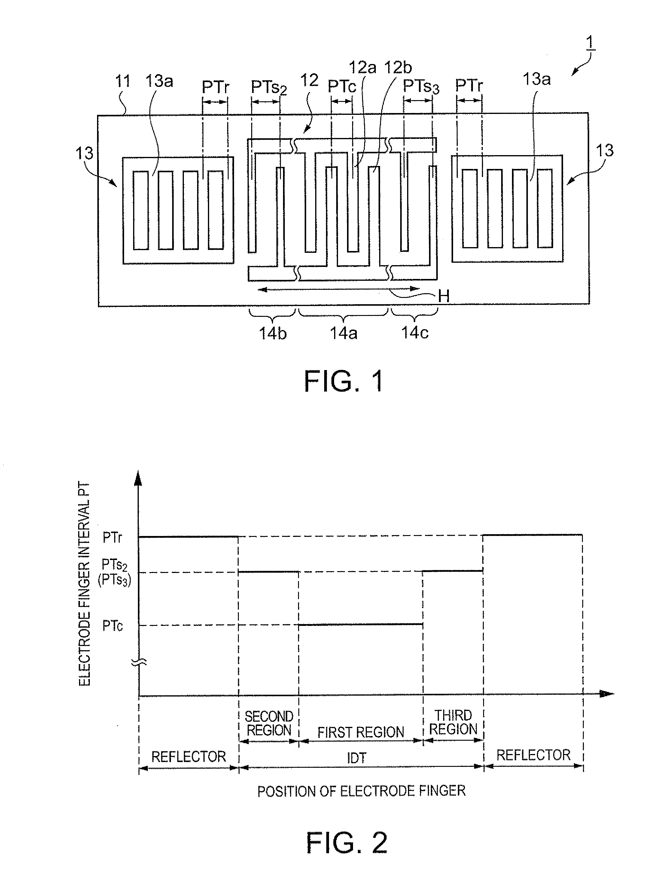
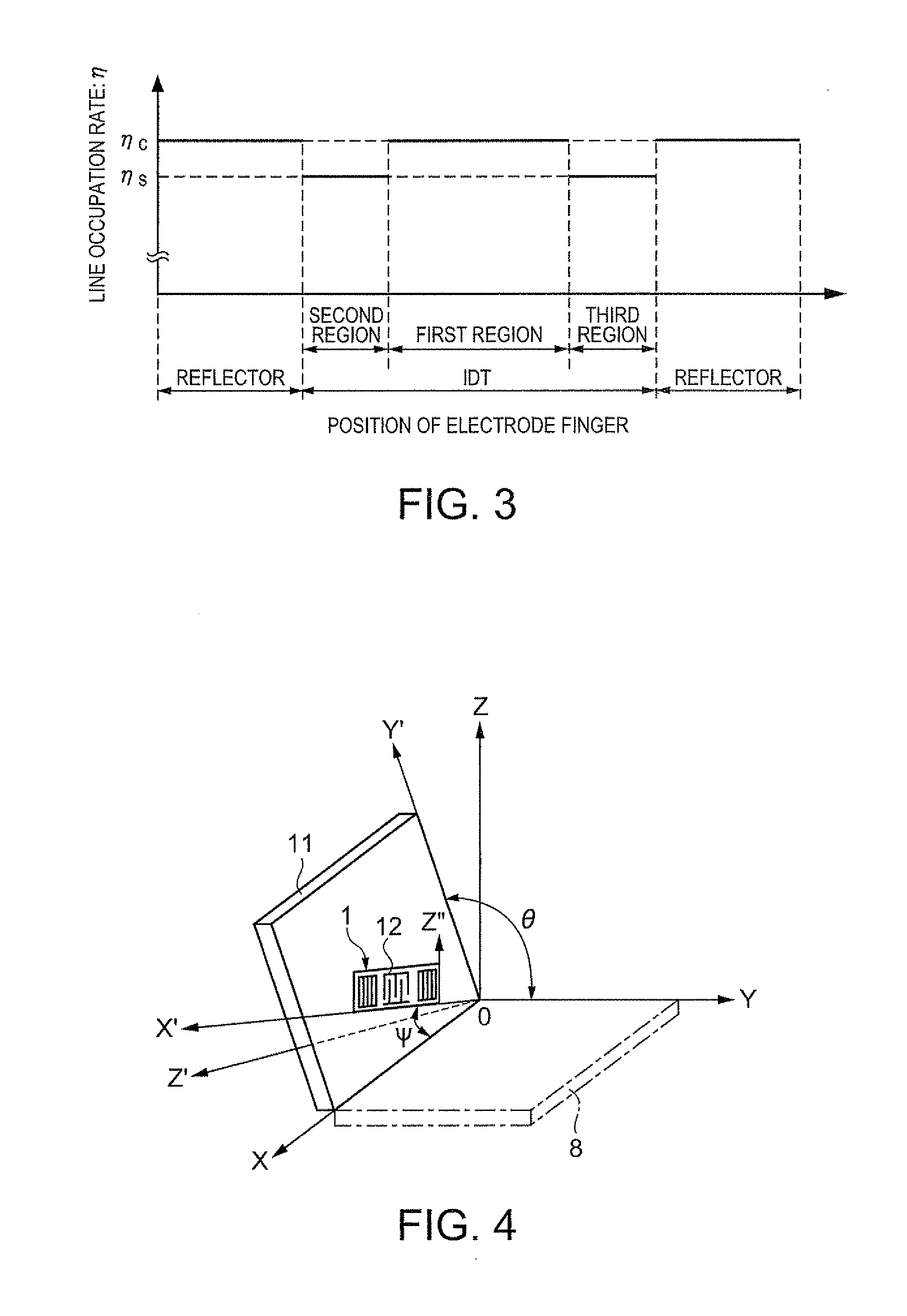
[0041]Next, a first embodiment of the invention will be described. FIG. 1 is a plan view schematically illustrating a structure of the surface acoustic wave resonator of the present embodiment. FIG. 2 is a diagram illustrating a relationship between a position of the electrode finger and the electrode finger interval. FIG. 3 is a diagram illustrating a relationship between the position of the electrode finger and the line occupation rate. FIG. 4 is a diagram illustrating a cutout angle of a quartz substrate and a surface acoustic wave propagation direction thereof.
[0042]As FIG. 1 shows, a surface acoustic wave resonator 1 includes an IDT 12 composed of interdigital electrodes and a pair of reflectors 13 formed in a manner sandwiching the IDT 12 in the propagation direction of a surface acoustic wave. The IDT 12 and the reflectors 13 are arranged on a quartz substrate 11 serving as a piezoelectric substrate. In the surface acoustic wave resonator 1, a surface acoustic wave excited by...
second embodiment
[0055]A surface acoustic wave resonator of a second embodiment will be described. In the present embodiment, the surface acoustic wave propagation direction of the quartz substrate and values of the line occupation rate thereof are different from those in the first embodiment. The quartz substrate is made of an in-plane rotated ST cut quartz substrate whose cut surface and whose surface acoustic wave propagation direction are (−1° to +1°, 113° to 135°, −3° to 3°) when they are expressed by the Euler angle (φ, θ, Ψ). In the surface acoustic wave resonator, the IDT is arranged in a manner that the propagation direction of a surface acoustic wave is in the X axis (Ψ=0°±3°). Further, the electrode fingers intervals in each region of the IDT is the same as those in the first embodiment (refer to FIGS. 1 and 2), and descriptions of the structure of the surface acoustic wave resonator will be omitted.
[0056]FIG. 9 is a graph illustrating a relationship between the line occupation rate and e...
third embodiment
[0060]By mounting the surface acoustic wave resonator of any of the embodiment in a package, a surface acoustic wave oscillator can be configured. FIG. 11 is a sectional view schematically illustrating a surface acoustic wave oscillator including the surface acoustic wave resonator mounted in a package. A surface acoustic wave oscillator 30 includes a ceramic package 31, an IC chip 32, the surface acoustic wave resonator 1, a lid 37, and the like. Formed in the ceramic package 31 is a recess 38 that is opened. Formed in the ceramic package 31 is a seam ring 35 in a manner surrounding the recess 38. The seam ring 35 is formed of a metal material such as kovar, In addition, on the periphery surface of the ceramic package 31, an external connection electrode 36 is formed to make connection with the external such as a circuit substrate. Though it is not illustrated in the drawing, wiring lines are provided so as to couple the external connection electrode 36 to the inside of the recess ...
PUM
 Abstract
Description
Claims
Application Information
 - R&D
- Intellectual Property
- Life Sciences
- Materials
- Tech Scout
- Unparalleled Data Quality
- Higher Quality Content
- 60% Fewer Hallucinations
Browse by: Latest US Patents, China's latest patents, Technical Efficacy Thesaurus, Application Domain, Technology Topic, Popular Technical Reports.
© 2025 PatSnap. All rights reserved.Legal|Privacy policy|Modern Slavery Act Transparency Statement|Sitemap|About US| Contact US: help@patsnap.com


