Waveguide-type optical interferometer

a waveguide-type, optical interferometer technology, applied in the direction of optical waveguide light guide, optical elements, instruments, etc., can solve the problem of interferometer polarization dependence, inability to completely eliminate the polarization dependence of half-wave plate, and inability to enable interferometer to be polarization-independent, etc. problem, to achieve the effect of eliminating the polarization dependence, simple configuration and excellent mass production of optical circuits

Active Publication Date: 2010-04-29
NIPPON TELEGRAPH & TELEPHONE CORP
View PDF8 Cites 32 Cited by
  • Summary
  • Abstract
  • Description
  • Claims
  • Application Information

AI Technical Summary

Benefits of technology

[0052]The present invention makes it possible to achieve the optical circuit capable of elimination of the polarization dependence resulting from the light induced by polarization coupling. This invention may utilize the polarization rotator of simple configuration having a combination of the two half-wave plates or the waveguides having birefringence properties, thereby to a

Problems solved by technology

However, the method using such a half-wave plate as mentioned above cannot, in fact, completely eliminate the polarization dependence.
This method does not necessarily enable the interferometer to be polarization-independent, for input light in all states of polarization, such as light in various states of p

Method used


Image

  • Waveguide-type optical interferometer
  • Waveguide-type optical interferometer
  • Waveguide-type optical interferometer

Examples


first embodiment

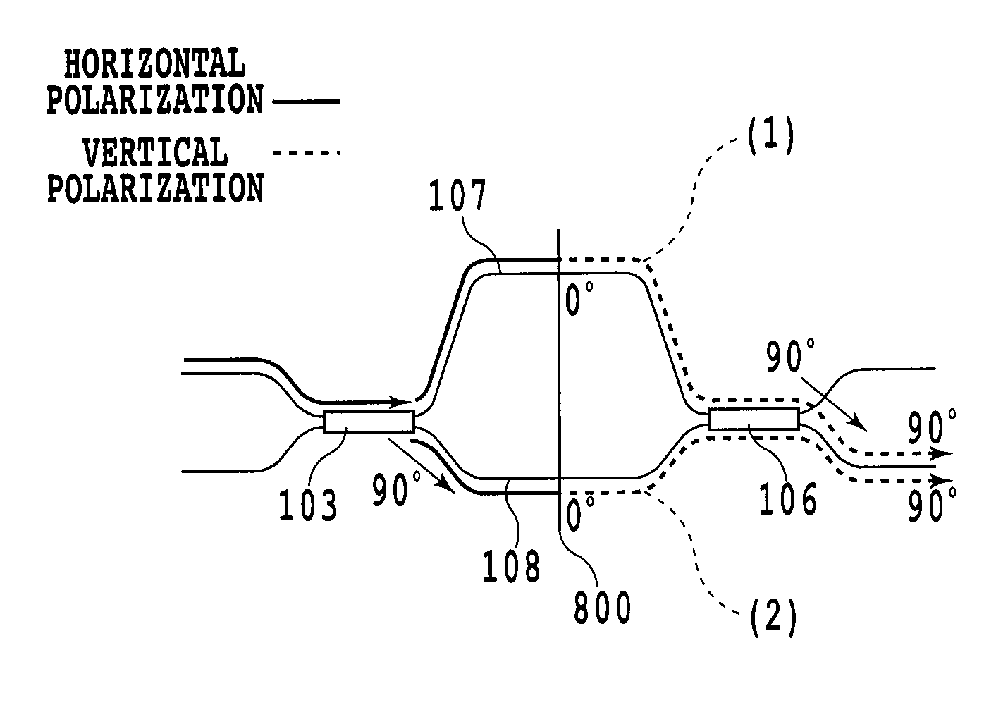
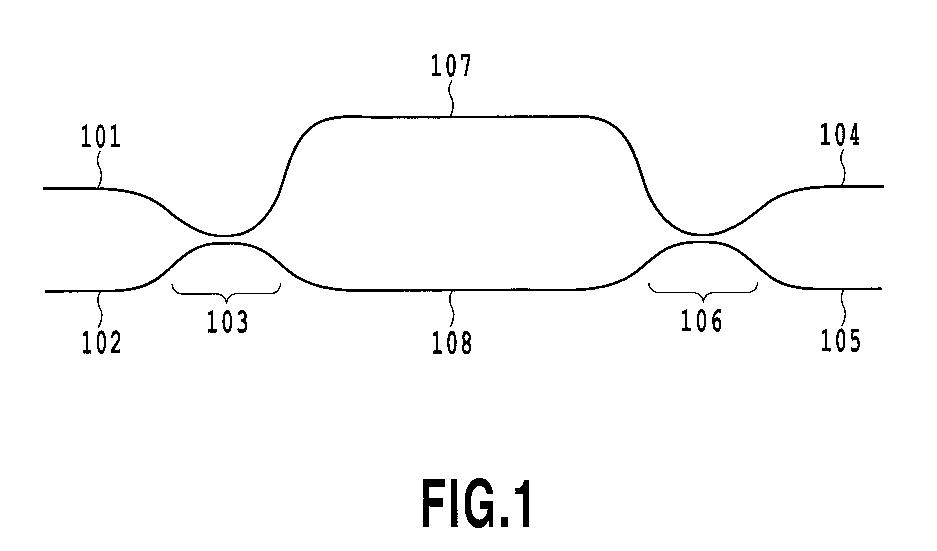
[0097]FIG. 9 is a diagram showing a waveguide-type optical interferometer according to the first embodiment of the present invention. An asymmetric MZI is configured by including an optical splitter 103 and an optical combiner 106 having a splitting ratio of 50%, and the two arm waveguides 107 and 108 of different lengths that provide a connection between the optical splitter 103 and the optical combiner 106. The long arm waveguide 107 and the short arm waveguide 108 are each formed of a multimode interference waveguide (MMI) and are birefringent. In the asymmetric MZI, a length between the two arm waveguides is adjusted so that FSR is 21 GHz. In the first embodiment, the polarization rotator is configured of a combination of two half-wave plates, that is, a first half-wave plate whose optic axis is inclined at 45° relative to the optic axes of the waveguides, and a second half-wave plate whose optic axis is parallel to the optic axes of the waveguides. Hereinafter, in order to dist...

second embodiment

[0109]FIG. 12 is a conceptual illustration showing the configuration of a polarization rotator according to the second embodiment, which implements the waveguide-type optical interferometer of the present invention. A different method from the first embodiment is used for the configuration in which the polarization rotator is implemented. The second embodiment is characterized in that a waveguide 121 having birefringence is placed on one side of a half-wave plate 122 thereby to operate the polarization rotator. Specifically, the waveguide may be designed so that the waveguide 121 in itself having the birefringence performs the function of providing the phase difference between vertical and horizontal polarizations, as in the case of the retarder described with reference to the first embodiment. The waveguide 121 corresponding to the retarder is configured in the interferometer, and thereby, the elimination of the polarization dependence of the interferometer can be achieved by the p...

third embodiment

[0131]As has been described in detail, the elimination of the polarization dependence of the interferometer caused by the light induced by polarization coupling produced in the directional coupler can be achieved by placing the polarization rotator in the optical path in the interferometer. However, it is demanded that the interferometer become polarization-independent over a wider range of wavelengths, depending on the field of application of the interferometer. In such a case, it is required that the interferometer be designed further allowing for the occurrence of interference in the arm waveguide.

[0132]The polarization rotator interposed in the interferometer effects any one of 90° rotation and −90° rotation of all polarizations propagating through the optical path. However, the polarization rotator has an optimum range of operating wavelengths, and thus, a wide range of wavelengths renders it difficult to perform accurate rotation operation for all wavelengths. Even if a match ...


PUM


Abstract

In an optical interferometer, polarization dependence attributable to the optical path difference has conventionally been eliminated by inserting a half-wave plate at the center of the interferometer. However, light induced by polarization coupling produced in directional couplers used in the optical interferometer causes interference having different interference conditions from those of the normal light. Polarization rotators that effect any one of 90° rotation and −90° rotation of all states of polarization of incoming light are inserted in the optical interferometer, and thereby the interference conditions of light induced by polarization coupling are made the same as those of the normal light. Each of the polarization rotators is implemented by using two half-wave plates and by varying an angle of combination of these half-wave plates. Alternatively, each of the polarization rotators is implemented through a combination of one half-wave plate and a waveguide having birefringence properties.

Description

TECHNICAL FIELD[0001]The present invention relates to a waveguide-type optical circuit and more particularly to a polarization-independent waveguide-type optical interferometer having no polarization dependence.BACKGROUND ART[0002]As the optical communication technology moves forward, development of optical components capable of directly processing optical signals becomes increasingly important. Above all, a waveguide-type optical interferometer utilizing interference of light in an optical waveguide structure integrated on a planar substrate is superior in mass production and has advantageous features such as low cost and high reliability. Typically included are an arrayed waveguide grating, a Mach-Zehnder interferometer, and a lattice circuit, for example.[0003]Standard photolithography and etching as well as glass deposition technology such as FHD (flame hydrolysis deposition) are used as a basic method for fabrication of the waveguide-type optical interferometer. A procedure for...

Claims


Application Information

Patent Timeline
IPC IPC(8): G02B6/27G02B6/26
CPCG02B6/12007G02B6/1228G02B2006/12159G02B2006/12116G02B6/126
Inventor NASU, YUSUKEOGUMA, MANABUHASHIZUME, YASUAKIINOUE, YASUYUKITAKAHASHI, HIROSHIHATTORI, KUNINORIHASHIMOTO, TOSHIKAZUSAKAMAKI, YOHEI
Owner NIPPON TELEGRAPH & TELEPHONE CORP
Why Eureka
Try Eureka