Imprinting mold and method of producing imprinting mold

a technology of imprinting mold and imprinting pattern, which is applied in the field of molds, can solve the problems of difficult to form pattern features of 100 nm or less, limited resolution of photolithography, and lack of direct writing by electron beams

Inactive Publication Date: 2010-05-06
PIONEER CORP
View PDF9 Cites 28 Cited by
  • Summary
  • Abstract
  • Description
  • Claims
  • Application Information

AI Technical Summary

Benefits of technology

[0003]However, in the case of forming a recess / protrusion surface in subject-to-shaping material such as a resist using a conventional mold, when forming a recess / protrusion pattern with regions where the area occupied by recesses is larger than that occupied by protrusions and regions where the former is smaller than the latter being mixed, namely, when forming a recess / protrusion surface having a plurality of regions different in recess / protrusion area ratio by imprint, it is difficult to form a desired pattern in subject-to-shaping material. Details thereof will be described below with reference to FIGS. 1 and 2.

Problems solved by technology

However, with these lithography technologies, there are respective problems.
First, because the photolithography has a limit to its resolution due to the light wavelength, it is difficult to form pattern features of 100 nm or less.
The direct writing by an electron beam is lacking in throughput per unit time and hence is not suitable for mass production.

Method used


Image

  • Imprinting mold and method of producing imprinting mold
  • Imprinting mold and method of producing imprinting mold
  • Imprinting mold and method of producing imprinting mold

Examples


embodiment 1

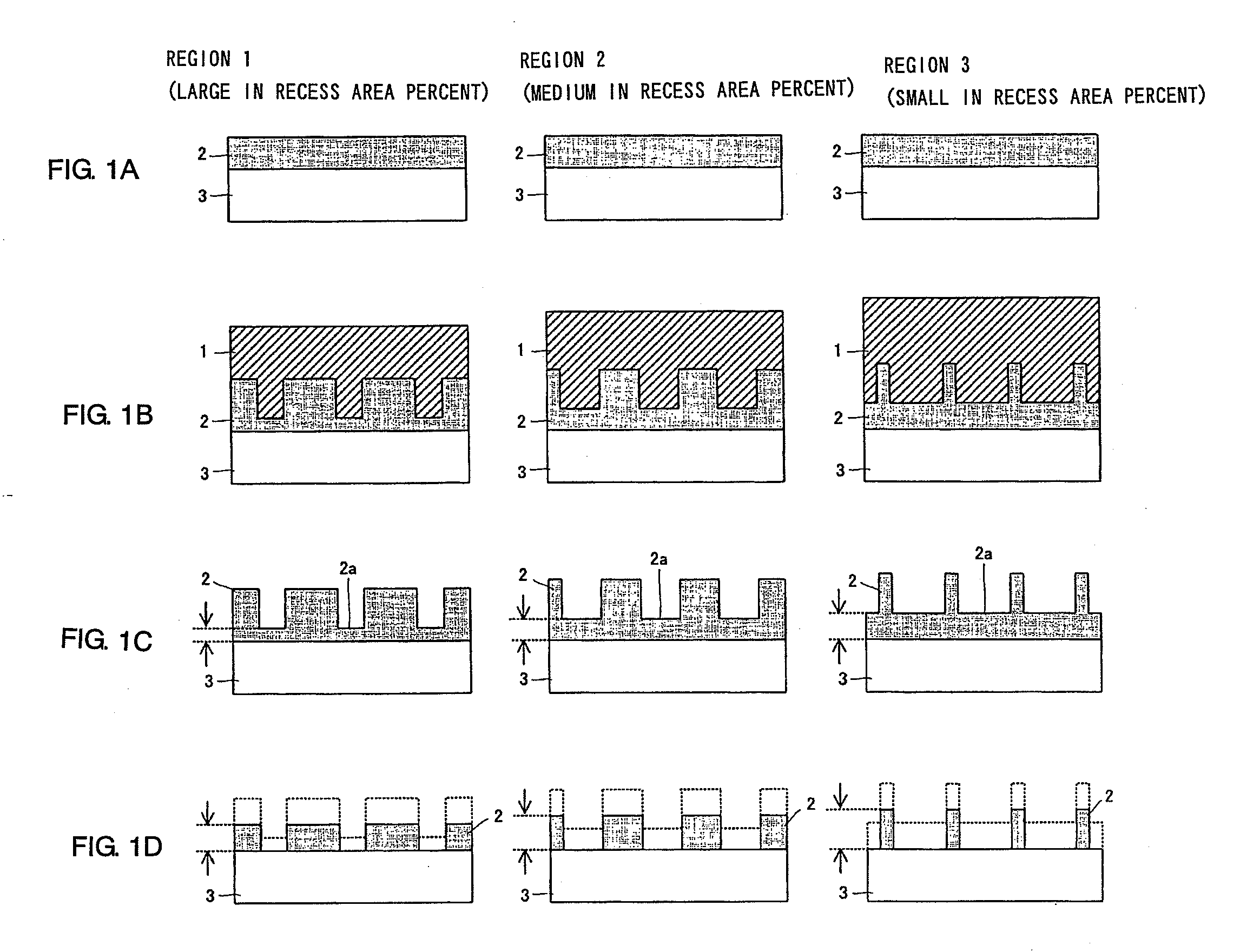
[0046]A first embodiment of the method of producing a mold according to the present invention will be described with reference to FIG. 6. First, a mold substrate forming the base of the mold to be produced is prepared. A substrate 30 made of, e.g., silicon, ceramic, or the like and uniformly coated with an NIL resist 20 as a transfer layer by, e.g., a spin coat method is used as the mold substrate. As the NIL resist 20, light curing resin or thermoplastic resin can be used, and in this embodiment, thermoplastic resin is used. As the thermoplastic resin, for example, polymethyl methacrylate (PMMA) or polystyrene (PS) can be used (FIG. 6 (a)).

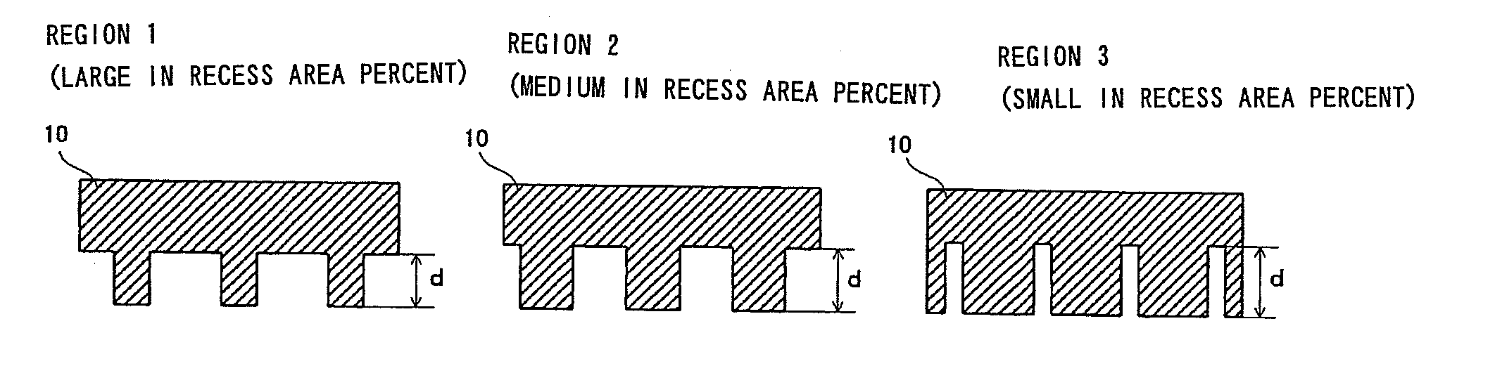
[0047]Then, the substrate 30 coated with the NIL resist 20 is heated to about 200° C. to soften the NIL resist 20. Next, a conventional mold 1, where a recess / protrusion surface made up of a plurality of regions different in recess / protrusion area ratio is formed, is put in contact with the softened NIL resist 20, and by applying pressure, the NI...

embodiment 2

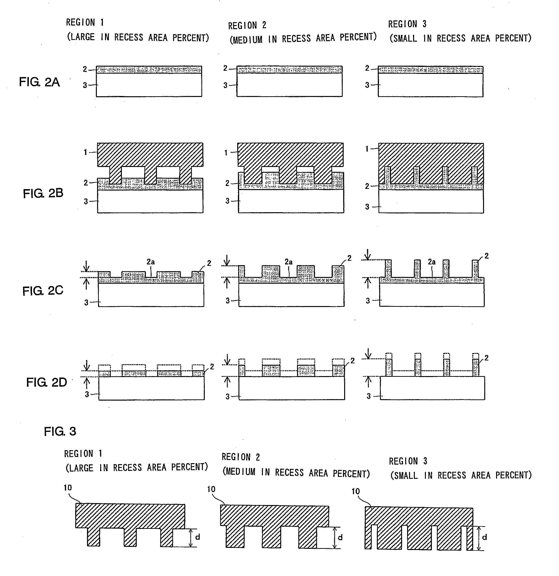
[0054]A second embodiment of the method of producing a mold according to the present invention will be described with reference to FIG. 7. First, a mold substrate forming the base of the mold to be produced is prepared. A substrate 30 uniformly coated with an NIL resist 20 as a transfer layer by, e.g., a spin coat method is used as the mold substrate. As the NIL resist 20, light curing resin or thermoplastic resin can be used, and in this embodiment, thermoplastic resin is used. As the thermoplastic resin, for example, polymethyl methacrylate (PMMA) or polystyrene (PS) can be used (FIG. 7 (a)).

[0055]Then, the substrate 30 coated with the NIL resist 20 is heated to about 200° C. to soften the NIL resist 20. Next, a conventional mold 1, where a recess / protrusion surface made up of a plurality of regions different in recess / protrusion area ratio is formed, is put in contact with the softened NIL resist 20, and by applying pressure, the NIL resist 20 is deformed. Then, keeping the mold ...

embodiment 3

[0063]A third embodiment of the method of producing a mold according to the present invention will be described with reference to FIG. 8. First, a mold substrate forming the base of the mold to be produced is prepared. A substrate 30 uniformly coated with an NIL resist 20 as a transfer layer by, e.g., a spin coat method is used as the mold substrate. As the NIL resist 20, light curing resin or thermoplastic resin can be used, and in this embodiment, thermoplastic resin is used. As the thermoplastic resin, for example, polymethyl methacrylate (PMMA) or polystyrene (PS) can be used (FIG. 8 (a)).

[0064]Then, the substrate 30 coated with the NIL resist 20 is heated to about 200° C. to soften the NIL resist 20. Next, a conventional mold 1, where a recess / protrusion surface made up of a plurality of regions different in recess / protrusion area ratio is formed, is put in contact with the softened NIL resist 20, and by applying pressure, the NIL resist 20 is deformed. Then, keeping the mold p...


PUM

PropertyMeasurementUnit
widthsaaaaaaaaaa
temperatureaaaaaaaaaa

Abstract

An imprinting mold having a recess/protrusion surface. The recess/protrusion surface is made up of a plurality of regions different in the ratio of the area of recesses to the area of protrusions, and a recess/protrusion surface of a region where the recess area percentage is relatively small is formed deeper in recess/protrusion depth than a recess/protrusion surface of a region where the recess area percentage is relatively large.

Description

TECHNICAL FIELD[0001]The present invention relates to a mold used in nano-imprint lithography (NIL) and a method of producing the same.BACKGROUND ART[0002]As a lithography technology usually used for patterning, there exists photolithography, and for the manufacture of a variety of products in small quantities, there exist direct writing by an electron beam, and so on. However, with these lithography technologies, there are respective problems. First, because the photolithography has a limit to its resolution due to the light wavelength, it is difficult to form pattern features of 100 nm or less. The direct writing by an electron beam is lacking in throughput per unit time and hence is not suitable for mass production. In order to overcome the fine-pattern limit and processing capacity of the lithography technology that is the core of these fine structure device making technologies, research into lithography by new means is being actively conducted. In particular, research into nano...

Claims


Application Information

Patent Timeline
Patent Type & Authority Applications(United States)
IPC IPC(8): B44C1/22B29C59/02
CPCB29C33/3878B29C33/42B29C59/022B29C2059/023B82Y10/00B82Y40/00G03F7/0002
Inventor KASONO, OSAMU
Owner PIONEER CORP
Why Eureka
Try Eureka