Magnetic memory element utilizing spin transfer switching

a technology of magnetic memory element and spin transfer switching, which is applied in the field of magnetic memory element utilizing spin transfer switching, can solve problems such as and achieve the effect of effectively reducing the critical current density

Active Publication Date: 2010-05-06
IND TECH RES INST
View PDF10 Cites 23 Cited by
  • Summary
  • Abstract
  • Description
  • Claims
  • Application Information

AI Technical Summary

Benefits of technology

[0012]Accordingly, the present invention provides a magnetic memory element utilizing spin transfer switching structure capable of reducing a critical current density effectively.

Problems solved by technology

Therefore, how to enhance write selectivity and reduce write currents have always been the most notable obstacles developing magnetic memories has ever encountered.
However, in order to continue enhancing the performance of the STT-RAM, how to reduce the critical current density and maintain sufficient thermal stability in the STT-RAM are still urgent issues to be resolved.

Method used


Image

  • Magnetic memory element utilizing spin transfer switching
  • Magnetic memory element utilizing spin transfer switching
  • Magnetic memory element utilizing spin transfer switching

Examples


Embodiment Construction

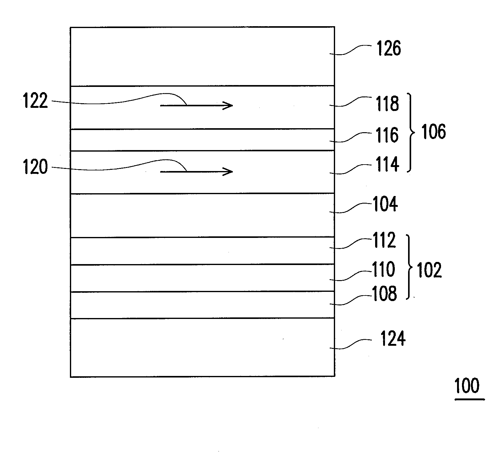
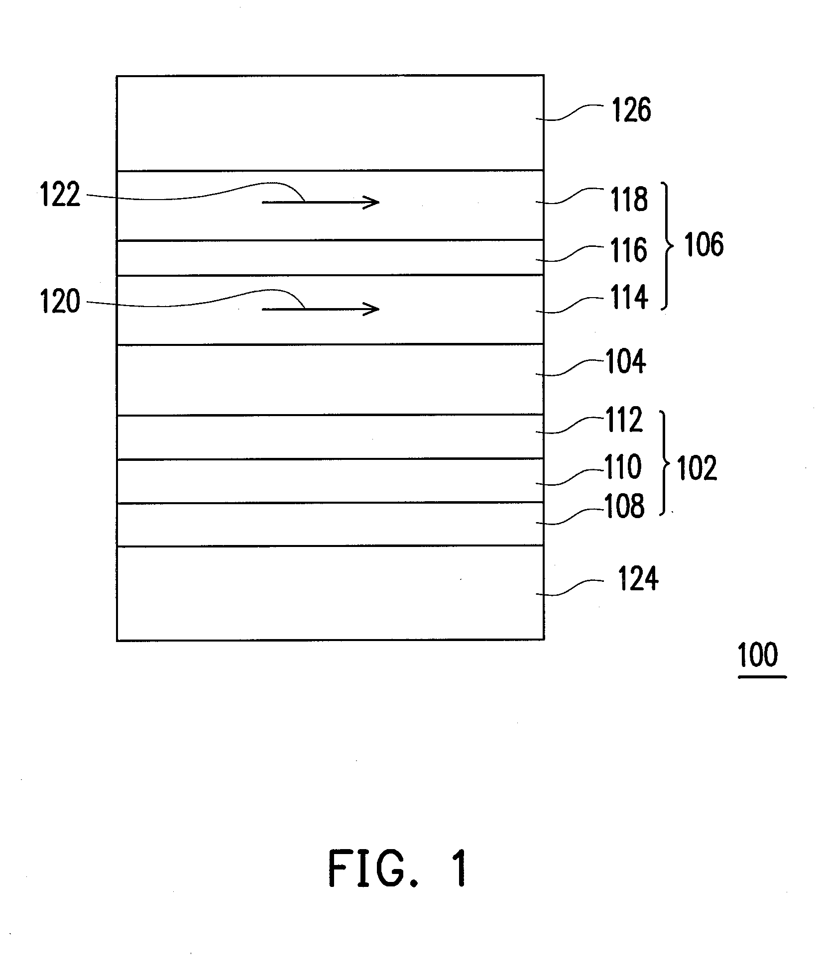
[0028]FIG. 1 is a schematic cross-sectional view of the magnetic memory element utilizing spin transfer switching according to the first embodiment of the present invention.

[0029]Referring to FIG. 1, a magnetic memory element 100 utilizing spin transfer switching includes a pinned layer 102, a tunneling barrier layer 104 and a free layer structure. According to the present embodiment, the free layer structure is, for example, a composite free layer 106.

[0030]The pinned layer 102 is a stacked layer of ferromagnetic / non-magnetic metal / ferromagnetic material constituted by a lower pinned layer 108, a coupling layer 110 and an upper pinned layer 112. Magnetization vectors of the lower pinned layer 108 and the upper pinned layer 112 are arranged as anti-parallel-coupled and not changed by operating magnetic fields. It should be noted that the pinned layer 102 depicted in FIG. 1 in the form of a multi-layered structure is provided for illustration purposes, and is not construed as limitin...


PUM


Abstract

A magnetic memory element utilizing spin transfer switching includes a pinned layer, a tunneling barrier layer and a free layer structure. The tunneling barrier layer is disposed on the pinned layer. The free layer structure includes a composite free layer. The composite free layer includes a first free layer, an insert layer and a second free layer. The first free layer is disposed on the tunneling barrier layer and has a first spin polarization factor and a first saturation magnetization. The insert layer is disposed on the first free layer. The second free layer is disposed on the insert layer and has a second spin polarization factor smaller than the first spin polarization factor and a second saturation magnetization smaller than the first saturation magnetization. Magnetization vectors of the first free layer and the second free layer are arranged as parallel-coupled.

Description

CROSS-REFERENCE TO RELATED APPLICATION[0001]This application claims the priority benefit of Taiwan application serial no. 97142204, filed on Oct. 31, 2008. The entirety of the above-mentioned patent application is hereby incorporated by reference herein and made a part of specification.BACKGROUND OF THE INVENTION[0002]1. Field of the Invention[0003]The present invention is related to a magnetic memory element, and in particular to a magnetic memory element utilizing spin transfer switching.[0004]2. Description of Related Art[0005]The magnetic random access memory (MRAM) has the advantages such as non-volatility, high density, high reading and writing speeds, and radiation resistance. When the conventional magnetic memory writes data, generally a magnetic memory cell selected by the intersection of induction magnetic fields of a write bit line (BL) and a write word line (WWL) is used to change a magnetoresistance (MR) of the magnetic memory by changing a magnetized vector direction o...

Claims


Application Information

Patent Timeline
Patent Type & Authority Applications(United States)
IPC IPC(8): H01L29/82
CPCG11C11/161H01L43/08H10N50/10
Inventor CHEN, WEI-CHUANYEN, CHENG-TYNGWANG, DING-YEONG
Owner IND TECH RES INST
Why Eureka
Try Eureka