
Determining Average Current Drawn by a Motor

a technology of average current and electric motor, which is applied in the direction of motor/generator/converter stopper, dynamo-electric converter control, instruments, etc., can solve the problems of extra components, cost impact, and difficulty in providing an accurate measurement of average valu

Active Publication Date: 2010-05-06
TRW LIMITED
View PDF8 Cites 3 Cited by
  • Summary
  • Abstract
  • Description
  • Claims
  • Application Information

AI Technical Summary

Benefits of technology

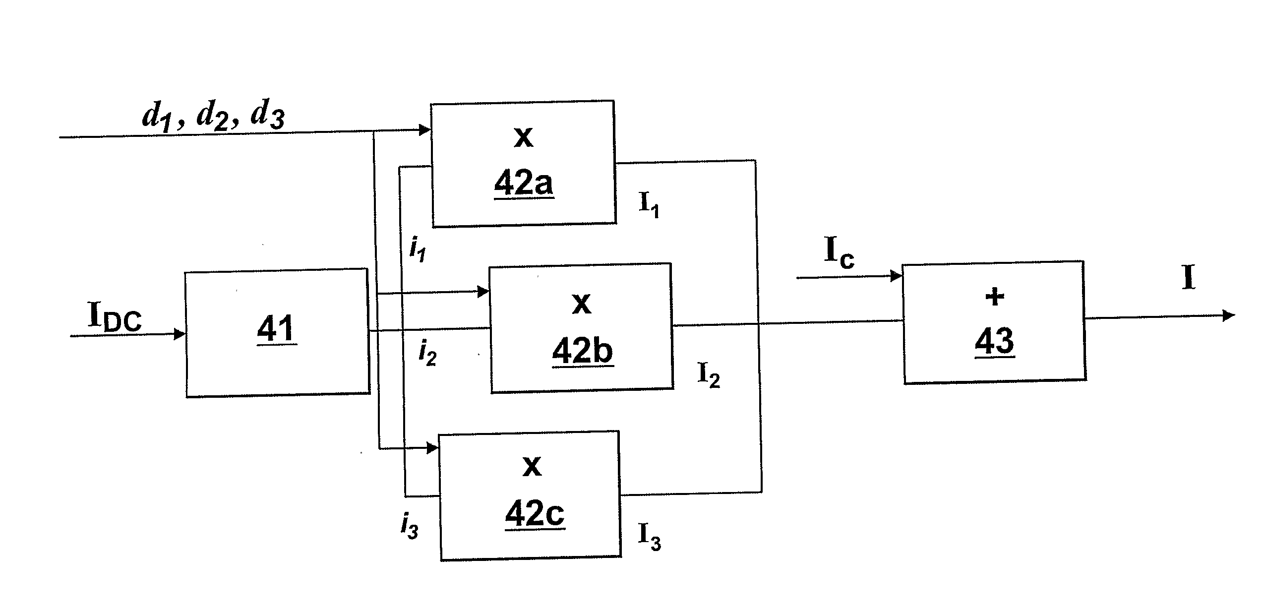
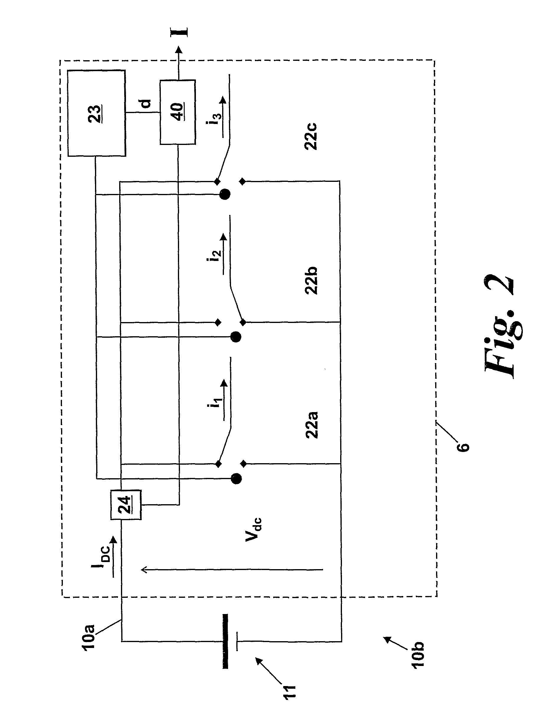
The patent describes a method and system for determining the average current drawn by an electric motor using a single current sensor. This is achieved by driving each phase of the motor with cyclic pulse width modulated (PWM) drive signals, and measuring the current flowing through each phase at an instant in the cycle. The system includes a current sensing circuit for each phase, which takes a measurement of the current at the same time as the PWM drive signals are applied. The duty ratio of the PWM drive signals indicates the ratio of time spent in the first and second states within a cycle. By combining the current measurements from each phase, an average current can be determined over a whole cycle. This approach is simple and does not require any additional hardware.

Problems solved by technology

However, such an approach is not trivial since the switching dynamics on the signal and noise make it difficult to provide an accurate measurement of the average value.
Furthermore, this requires extra components, which can have an impact on costs.
However, this is unnecessarily complicated, and for accurate current predication requires knowledge of both voltage and current phases and magnitudes, resistances and inductances of the motor, rotor position and battery voltage.

Method used


Image

  • Determining Average Current Drawn by a Motor
  • Determining Average Current Drawn by a Motor
  • Determining Average Current Drawn by a Motor

Examples


Embodiment Construction

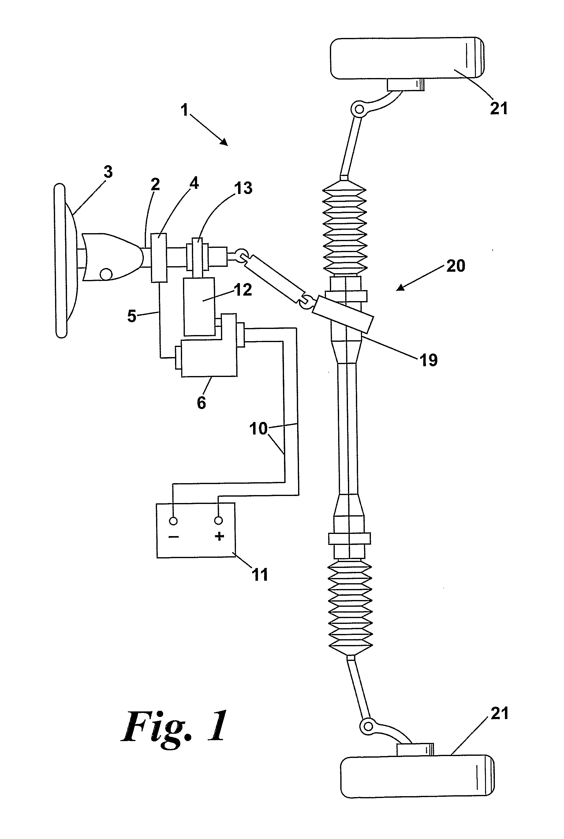
[0039]FIG. 1 shows an electric power assisted steering system according to the present invention. This shows a steering mechanism 20 for a vehicle, comprising a steering wheel 3 coupled to a steering shaft 2. The shaft 2 engages a steering rack 19 such that rotation of the wheel 3 and hence the shaft 2 drives steering rack 19 laterally. Such movement of the rack 19 causes the wheels 21 to rotate about a roughly vertical axis, as is well known in the art.

[0040]In order to assist the driver, an assistance motor 12 is provided. This is coupled to shaft 2 by means of a gearbox and coupling 13. The motor 12 is provided with a drive circuit 6, which takes current from battery 11 in order to drive motor 12. A torque sensor 4 on steering shaft 2 senses the level of torque in the steering shaft and transmits the measured torque level to drive circuit 6. This then causes the motor 12 to apply an amount of assistance torque to the steering shaft 2 and hence helps the driver of a vehicle turn t...


PUM


Abstract

A method of determining the average current drawn by an electric motor, the motor comprising a plurality of phases, the method comprising: driving each phase of the motor with cyclic pulse width modulated drive signals having a first state and a second state, and a duty ratio indicative of the ratio of time spent in the first to second states within a cycle, determining the current flowing through each phase at an instant in the cycle; and determining the average current drawn by the motor over at least one cycle by combining the currents flowing through each phase with the duty ratios for each phase. The method may be embodied in a combination of a motor and a drive circuit for the motor, such as can be used in an Electric Power Assisted Steering system.

Description

CROSS-REFERENCE TO RELATED APPLICATIONS[0001]This application is a national stage of International Application No. PCT / GB2008 / 000898 filed Mar. 14, 2007, the disclosures of which are incorporated herein by reference, and which claimed priority to Great Britain Patent Application No. 0704877.0 filed Mar. 14, 2007, the disclosures of which are incorporated herein by reference.BACKGROUND OF THE INVENTION[0002]This invention relates to a method of determining the average current drawn by an electric motor, and to related apparatus.[0003]In many automotive applications, it is useful to be able to provide a measure of the battery current draw whilst a system is in operation. For large electrical components such as an electric power assisted steering (EPAS) system, it is common to transmit the battery current information to other components on the vehicle to enable load-levelling to be carried out to improve battery / alternator performance.[0004]For cost-sensitive automotive applications, t...

Claims


Application Information

Patent Timeline
Patent Type & Authority Applications(United States)
IPC IPC(8): H02P23/14
CPCB62D5/046B62D5/0481H02M2001/009H02P6/28H02M7/5395Y02E20/16H02M1/009B62D5/04H02P23/14H02P27/08
Inventor LI, JIANG
Owner TRW LIMITED
Learn More