
Controlling a power of an electrical motor

a technology of electrical motor and power supply, which is applied in the direction of electronic commutation motor control, motor/generator/converter stopper, dynamo-electric converter control, etc., can solve the problem of reducing the life of brushes, and achieve the effect of prolonging the life of brushes

Active Publication Date: 2010-05-06
KONINKLIJKE PHILIPS ELECTRONICS NV
View PDF7 Cites 2 Cited by
  • Summary
  • Abstract
  • Description
  • Claims
  • Application Information

AI Technical Summary

Benefits of technology

[0003]It is an object of the invention to provide a power control of an AC motor with a longer lifetime of the brushes.
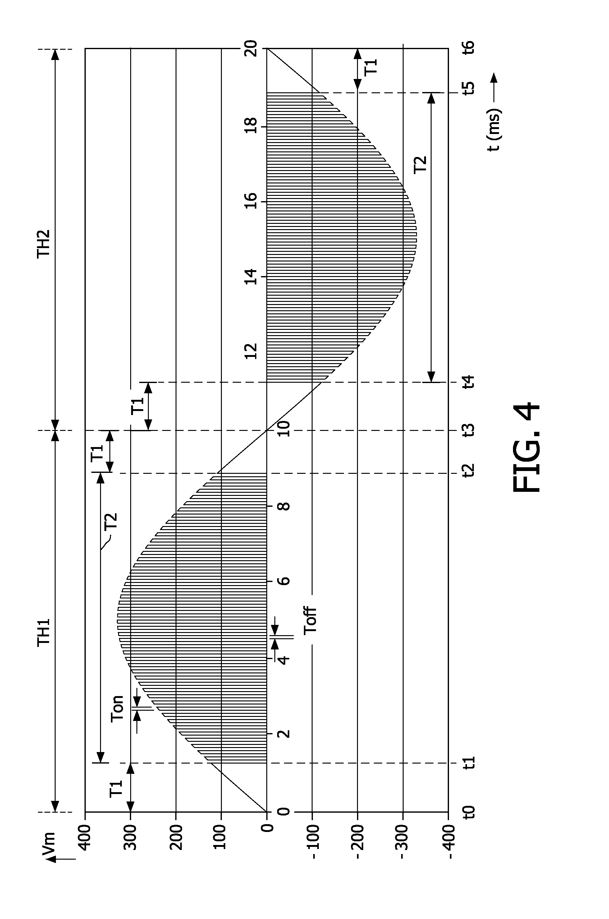
[0008]For series motors of which the stator and / or rotor is sufficiently in magnetic saturation, the variation of the magnetic flux as function of a variation of the current through the motor is much less than if the motor is not in magnetic saturation. Or said differently, a particular delta-current through the motor causes a much larger delta-flux at small currents than at large currents. Consequently, if the pulse width modulation is affected at small currents, relatively large flux variations result. These large flux variations induce high voltages which cause high currents through the brushes and shorten the lifetime of the brushes. The present invention therefore first supplies the rectified input voltage to the motor without performing PWM to slowly build up sufficient current through the motor to obtain a sufficient high magnetic saturation before the PWM is activated. Thus, when the PWM is activated, due to the relatively high magnetic saturation, the induced voltages caused by the current variations through the motor are much lower and the life time of the brushes is longer.

Problems solved by technology

The control of the current through the motor with a triac has the disadvantage that the lifetime of the brushes decreases.

Method used


Image

  • Controlling a power of an electrical motor
  • Controlling a power of an electrical motor
  • Controlling a power of an electrical motor

Examples


Embodiment Construction

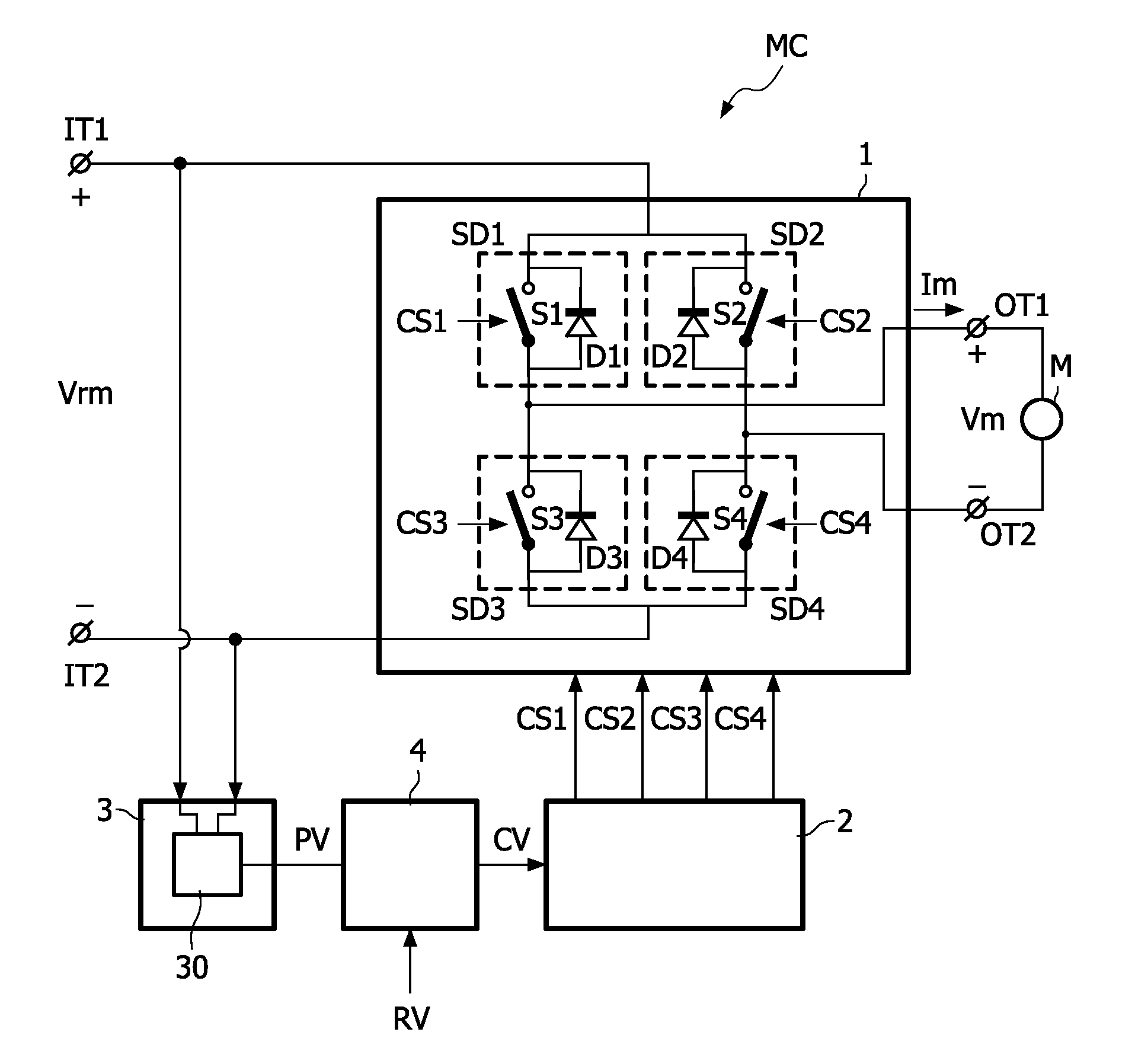
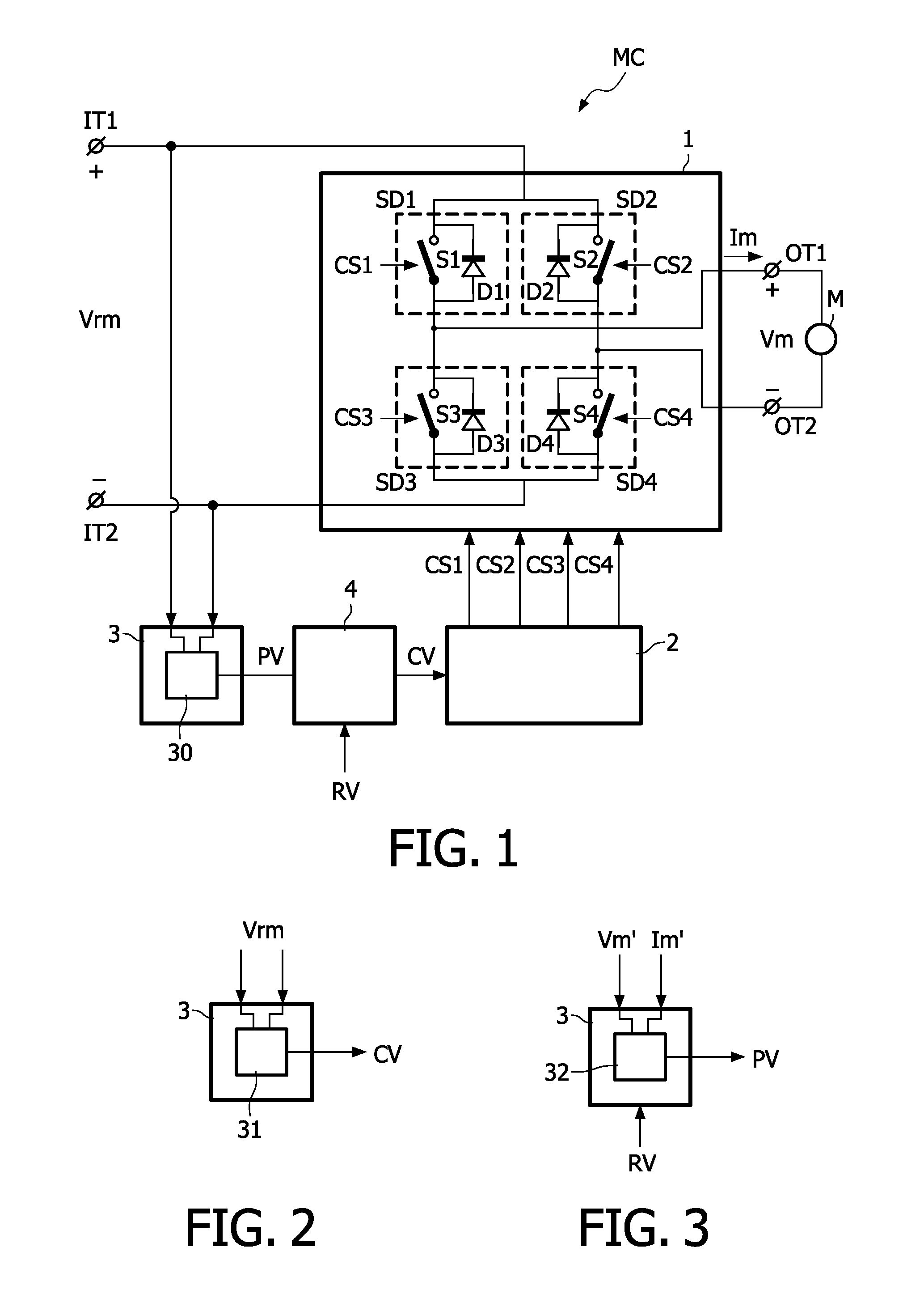
[0024]FIG. 1 schematically shows a circuit diagram of an embodiment of a motor system which comprises a motor control circuit MC and a motor M. The motor control circuit MC comprises input terminals IT1, IT2 to receive a rectified input voltage Vrm. Preferably, the rectified input voltage Vrm is an unbuffered rectified mains voltage. With unbuffered is meant not smoothed by capacitors. The motor M is coupled between output terminals OT1, OT2 of the motor control circuit MC.

[0025]A switching circuit 1 is arranged between the input terminals IT1, IT2 and the output terminals OT1, OT2 to intermittently couple the output terminals OT1, OT2 to the input terminals IT1, IT2. If the switching circuit 1 is in the on-state Ton (see FIG. 4 for the associated on-period of time), the rectified input voltage Vrm is coupled via the switching circuit 1 to the motor M to supply the AC drive voltage Vm and the drive current Im to the motor M. If the switching circuit 1 is in the off-state Toff (see F...


PUM


Abstract

A motor control circuit (MC) comprising input terminals (IT1, IT2) to receive a rectified input voltage (Vrm), and output terminals (OT1, OT2) to supply a motor drive signal (Vm). A switching circuit (1) is alternately in an on-state (Ton) and an off-state (Toff) for intermittently coupling the input terminals (IT1, IT2) to the output terminals (OT1, OT2). A controller (2) controls the switching circuit (1) to be (i) in the on-state (Ton) during a first period in time (T1) when an amount of magnetic saturation of the motor is smaller than a predetermined value, and (ii) alternately in the on-state (Ton) and the off-state (Toff) to obtain a pulse width control of the motor drive signal (Vm) during a second period in time (T2) when the amount of magnetic saturation of the motor is larger than the predetermined value.

Description

FIELD OF THE INVENTION[0001]The invention relates to a motor control circuit, a motor system comprising the motor control circuit, an appliance comprising the motor system, and a method of controlling a motor power.BACKGROUND OF THE INVENTION[0002]Power control of an AC series motors with a triac is well known. An example of a triac control circuit is disclosed in WO2006 / 033085A2. The control of the current through the motor with a triac has the disadvantage that the lifetime of the brushes decreases.SUMMARY OF THE INVENTION[0003]It is an object of the invention to provide a power control of an AC motor with a longer lifetime of the brushes.[0004]A first aspect of the invention provides a motor control circuit as claimed in claim 1. A second aspect of the invention provides a motor system as claimed in claim 8. A third aspect of the invention provides an appliance as claimed in claim 9. A fourth aspect of the invention provides a method of controlling a motor power as claimed in cla...

Claims


Application Information

Patent Timeline
IPC IPC(8): H02P29/00
CPCH02M1/40H02M7/2176H02P7/30H02P25/14
Inventor OTTEN, WESSEL ADOLFETTES, WILHELMUS
Owner KONINKLIJKE PHILIPS ELECTRONICS NV
Learn More