
Surgical bone clamp

a surgical and bone clamping technology, applied in the field of surgical bone clamps, can solve the problems of increasing the total length of surgery and the risk of complications for patients, affecting the safety of patients, and affecting the patient's recovery, so as to achieve convenient operation, simple construction, and large surface area

Inactive Publication Date: 2010-05-06
SNELL CHRISTOPHER
View PDF12 Cites 17 Cited by
  • Summary
  • Abstract
  • Description
  • Claims
  • Application Information

AI Technical Summary

Benefits of technology

[0012]The surgical bone clamp has a large surface area to engage, for example, the proximal portion of the tibia that is removed during knee surgery. The bone clamp is lightweight, is easily maneuverable and is designed to withstand the forces required to resect a portion of the proximal tibia in knee surgery. The bone clamp is of simple construction and provides a device that is economically feasible, long lasting and relatively trouble free in operation.
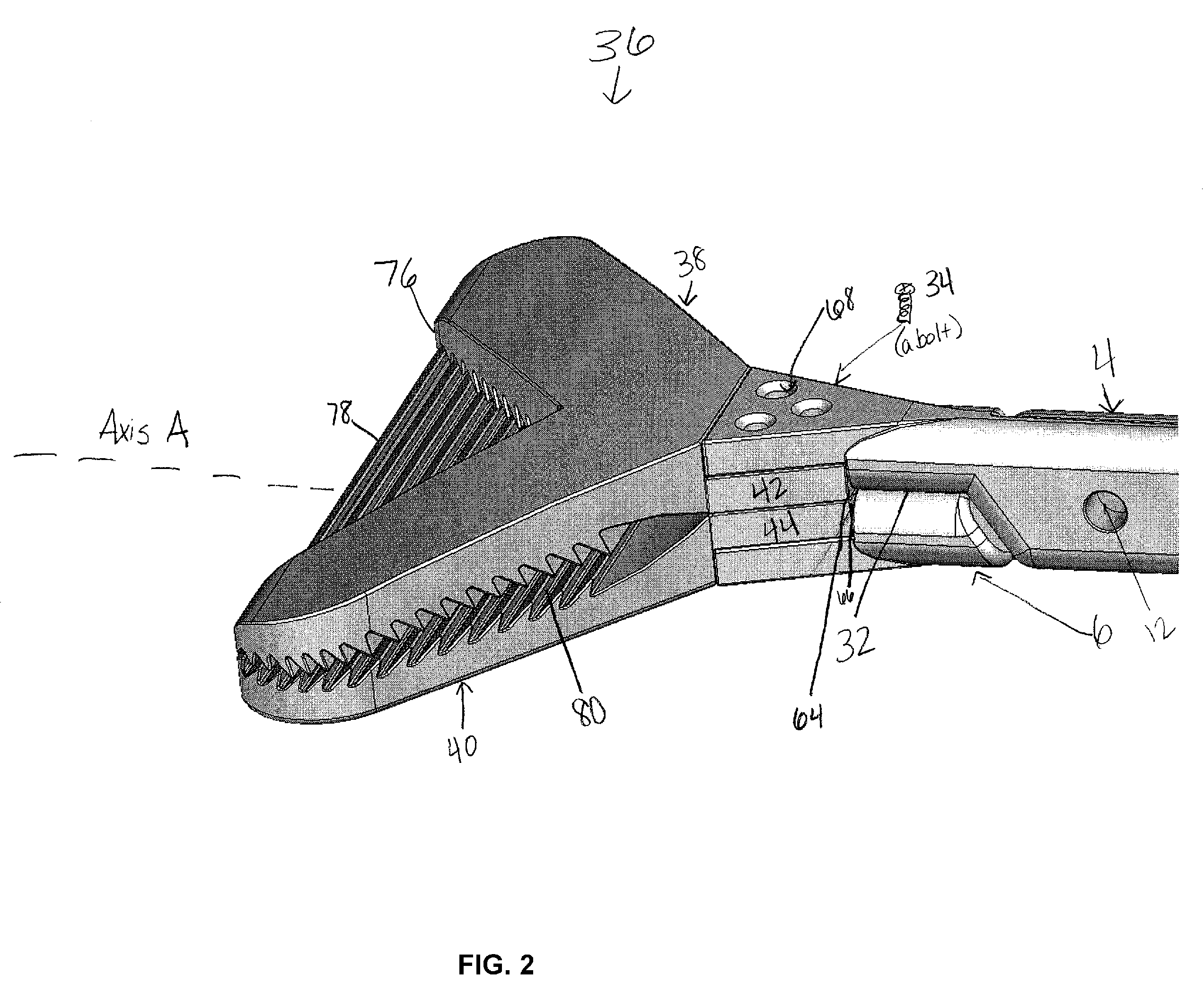
[0013]The bone clamp includes a handle portion, a ratchet locking portion, and a clamping portion. The handle portion includes first and second handle arms, pivotally connected to one another between first and second ends of each. Finger loops are provided at the first end of each handle arm for receiving a thumb or at least one opposing finger, such as a forefinger. Cooperating components of the ratcheting mechanism are carried on each finger loop proximate the first end of each, permitting a stepwise reduction in distance between the finger loops and between the second ends of the handle arms through the pivotal connection. The clamping portion comprises two serrated jaws, a split top jaw and a full bottom jaw, that engage the tibial bone piece and that facilitate resection of the proximal tibial head in total knee arthroplasty.

Problems solved by technology

As such, a surgeon must be very careful when removing tibial bone segments in total knee replacement, such as removing the proximal head of the tibia from the body cavity, as lack of a proper tool combined with improper use of another clamp may cause bone breakage or fragmentation.
Weakened bones are easier to break, making use of improperly designed clamps risky to the patient during knee arthroplasty.
If a clamp breaks the tibial piece during surgery, the bone must then be removed in multiple pieces, increasing both the total length of surgery and the risk of complications to the patient.
Some clamps may even cause fragmentation of weakened bones, and it is difficult and time-consuming for a surgeon to remove any resulting bone fragments from the body cavity.
None of these clamps is designed to engage the proximal tibia piece that is resected during knee replacement surgery.
These clamps, known in the prior art, may bend under excess force, require continued re-clamping to secure a good grip on the proximal portion of the tibia, deny the surgeon a high level of control, lack an adequate clamping range to engage the proximal portion of the tibia, or be generally too large or cumbersome to be practical for use in total knee replacement surgeries.
Another problem arises with the Backhaus clamp's effective clamping range, which is only about 1.0 to 5.0 mm, much smaller than the proximal portion of the tibia.
Additionally, the Backhaus clamp is not designed to withstand the forces necessary to resect bone, and the instrument often deforms under the forces used to resect a portion of the tibia.
On the other hand, the Hoff towel clamp does not readily puncture bone, but it is not large enough to engage both sides of the tibia to allow for easy resection.
The Hoff towel clamp does not have an adequate clamping range by which it can securely grip an object.
Its locking mechanism has a very limited range of use, and when significant force is applied, the instrument can become damaged or bent.
Furthermore, the Hoff clamp is difficult to use in knee surgery because its upper and lower jaws are equal in size, and each is difficult to insert beneath the tibia bone.
But the straight jaws of haemostatic forceps are not capable of making full contact with the tibial bone segment because to maximize contact with the object, the clamp works best with objects of only about 1.0 to 3.0 mm of thickness.
Bone forceps generally will not break a tibial portion, but they do not have the ability to grasp both tibia plateaus simultaneously, and they lack the refinement to clear the tibial spines, which may result in breaking the spines and producing bone fragments within the patient's body cavity.

Method used


Image

  • Surgical bone clamp
  • Surgical bone clamp
  • Surgical bone clamp

Examples


Embodiment Construction

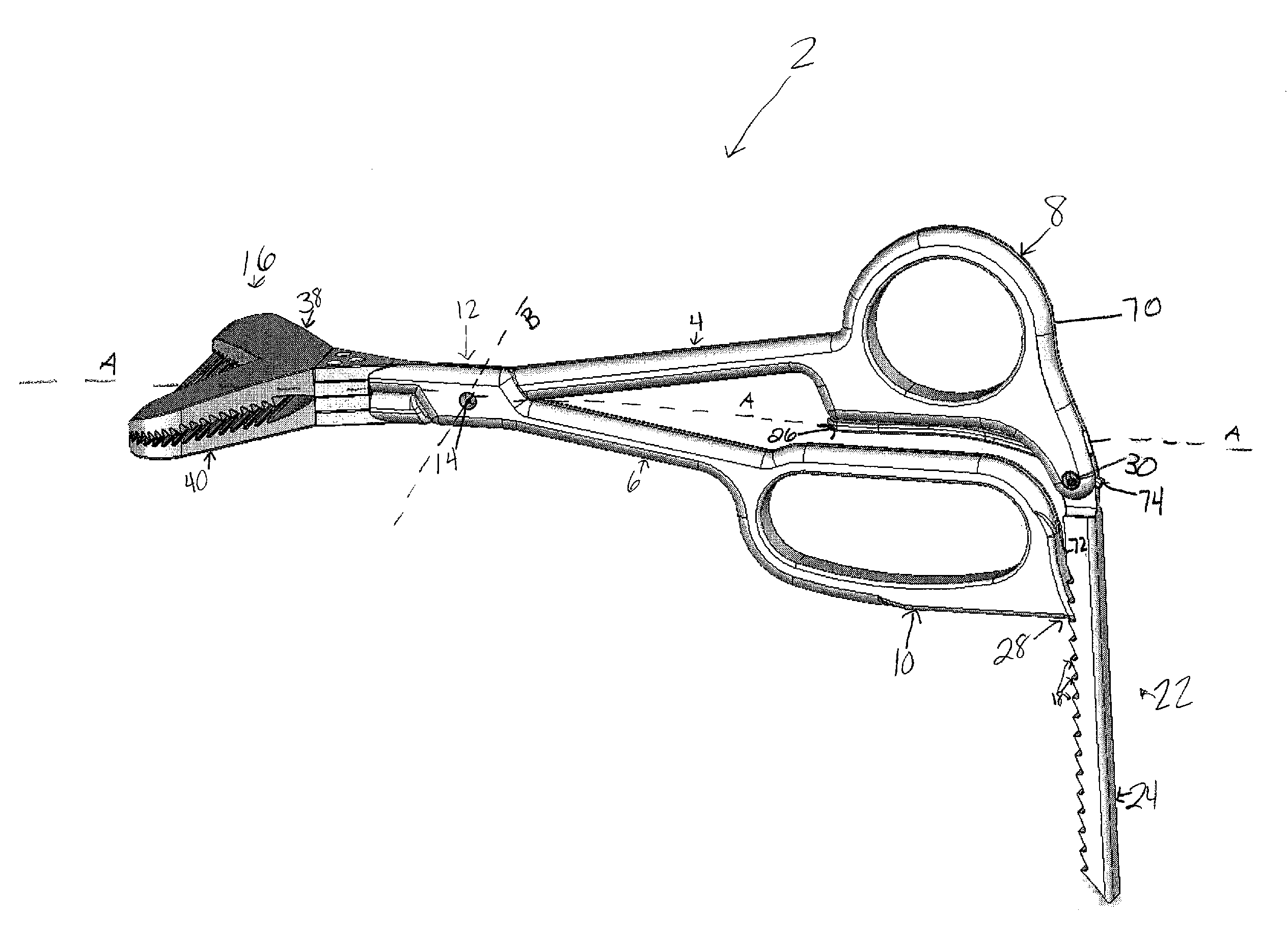
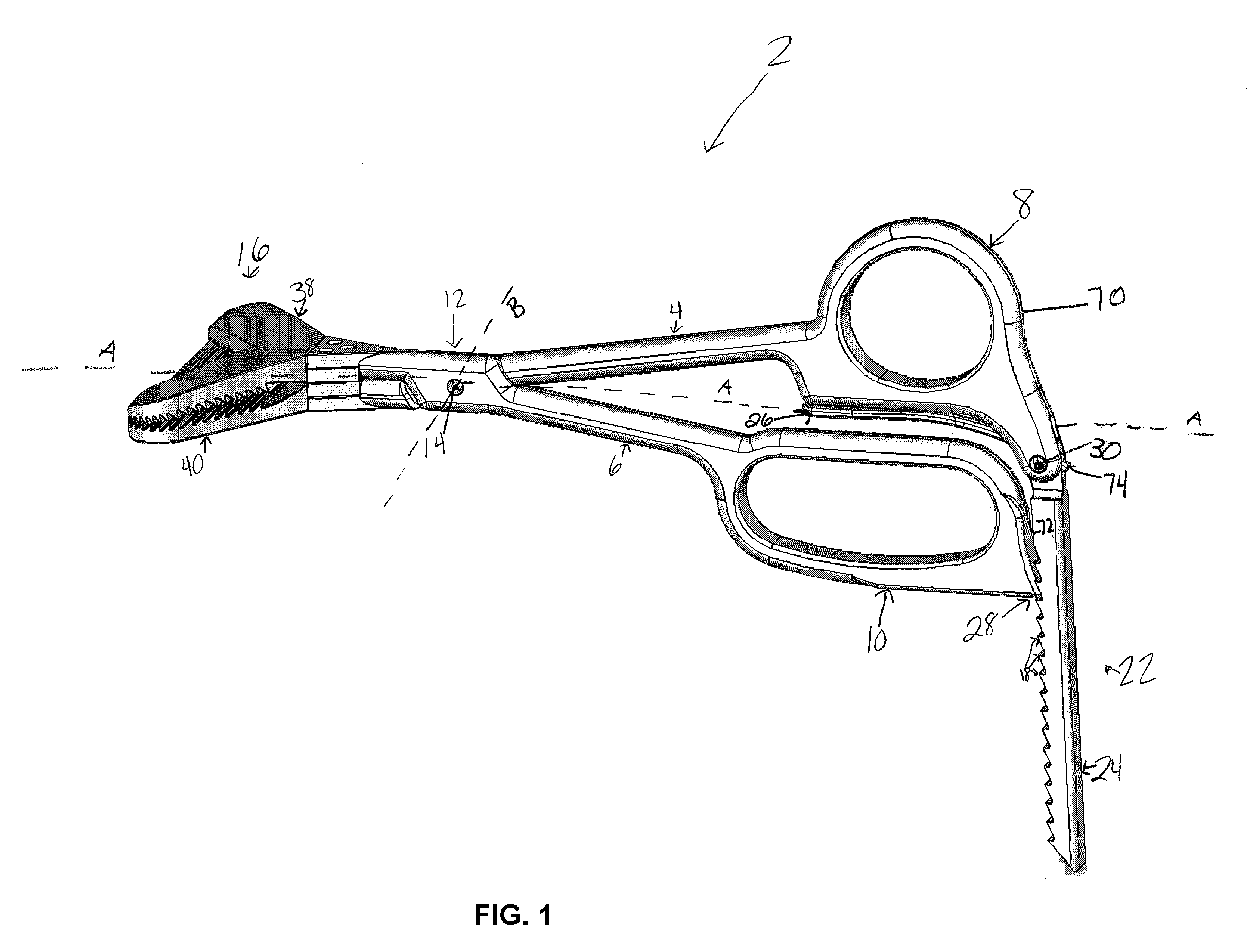
[0021]FIG. 1 illustrates generally a bone clamp 2 in accordance with the invention. The components of the bone clamp 2 are constructed of a suitable material that will allow for sterilization, will resist corrosion, and is of the type used for instruments of similar application, such as, for example, stainless steel.

[0022]A pair of handle arms 4 and 6 is hingedly and pivotally connected at a pivot joint 12 by a pivot pin 14. Handle arm 4 will be referred to as the first handle arm and handle arm 6 will be referred to as the second handle arm. The handle arms 4 and 6 are used to hold the device as well as manipulate the bone engaging means 16 within the surgical space. The pivot pin 14 forms an axis of rotation of the relative movement between the handle arms 4 and 6 so that the arms can pivot in a normal scissors or forceps fashion.

[0023]Finger loops 8 and 10 are provided at respective ends of handle arms 4 and 6 for transmission of a hand motion to the handle arms 4 and 6 and trans...


PUM


Abstract

The surgical bone clamp securely grasps and removes bone and other tissue during surgery, such as total knee replacement surgery. In one embodiment, the device includes a handle portion, a clamp portion, and a ratchet portion. The handle portion includes two handle arms that are pivotally connected, and the ratcheting portion permits the handle arms to be spaced at any one of a plurality of step settings. One of the handle arms provides a finger loop to engage the thumb, while the other handle arm provides a finger loop to engage at least one opposing finger. The clamp portion includes two serrated clamping jaws designed to engage the bone or other tissue surface and to provide adequate gripping force to allow for removal of the bone piece or tissue from the body cavity. The device provides significant mechanical advantage to the user, may be operated with one hand, and may include removable clamping jaws.

Description

FIELD OF THE INVENTION[0001]This invention generally pertains to a clamping device used in orthopedic surgery, with a particular embodiment of the invention being described, without limitation, in the context of total knee arthroplasty. More particularly, with respect to knee surgery, the invention relates to a bone clamp used to resect a proximal portion of the tibia.BACKGROUND OF THE INVENTION[0002]Total knee arthroplasty involves the replacement of a proximal portion of the tibia, a distal portion of the femur, and the posterior portion of the patella with artificial components. Specifically, an important part of total knee replacement involves resection of a proximal portion of the tibia. As used herein, the term “proximal” means closer to the heart and “distal” means further from the heart.[0003]During total knee replacement, the head of the tibia is cut away and resected, leaving the end of the tibia as a planar surface to complement an artificial knee component. The planar su...

Claims


Application Information

Patent Timeline
IPC IPC(8): A61B17/00A61B17/04
CPCA61B17/282A61B17/8866A61B2017/2808A61B2017/2837
Inventor SNELL, CHRISTOPHER
Owner SNELL CHRISTOPHER
Learn More