Apparatus for measurement of in-situ viscosity

a technology of viscosity and apparatus, which is applied in the direction of measurement devices, instruments, scientific instruments, etc., can solve the problems of reduced liquid volume, difficult to adapt to sealed vessels such as those used for enrichment cultures, and difficulty in adapting the type of viscometer to a sealed vessel

Inactive Publication Date: 2010-05-13
EI DU PONT DE NEMOURS & CO
View PDF6 Cites 30 Cited by
  • Summary
  • Abstract
  • Description
  • Claims
  • Application Information

AI Technical Summary

Problems solved by technology

This prior art methodology is believed disadvantageous because the sampling disturbs the environment of the culture and results in a reduction in liquid volume.
Although some viscometers can use volumes as low 10 cubic centimeters (cc), they are expensive, and are difficult to adapt to sealed vessels such as those used to incubate enrichment cultures.
This type of viscometer is difficult to adapt to a sealed vessel such as those used to incubate enrichment cultures.
Although potentially adaptable to sealed vessels such as those used to incubate enrichment cultures, a difficulty is encountered with using a spherical ball and controlling its location in order to keep it within the hydrocarbon phase of a multi-phase enrichment culture.
Prior art apparatus suffer from a number of deficiencies.
Prior art apparatus typically do not provide a means to measure the viscosity as a function of rate of shear.
The falling ball technique provides no means to independently agitate the fluid in the sealed vessel without disturbing the movement of the spherical ball that is used to measure viscosity.

Method used


Image

  • Apparatus for measurement of in-situ viscosity
  • Apparatus for measurement of in-situ viscosity
  • Apparatus for measurement of in-situ viscosity

Examples


example 1

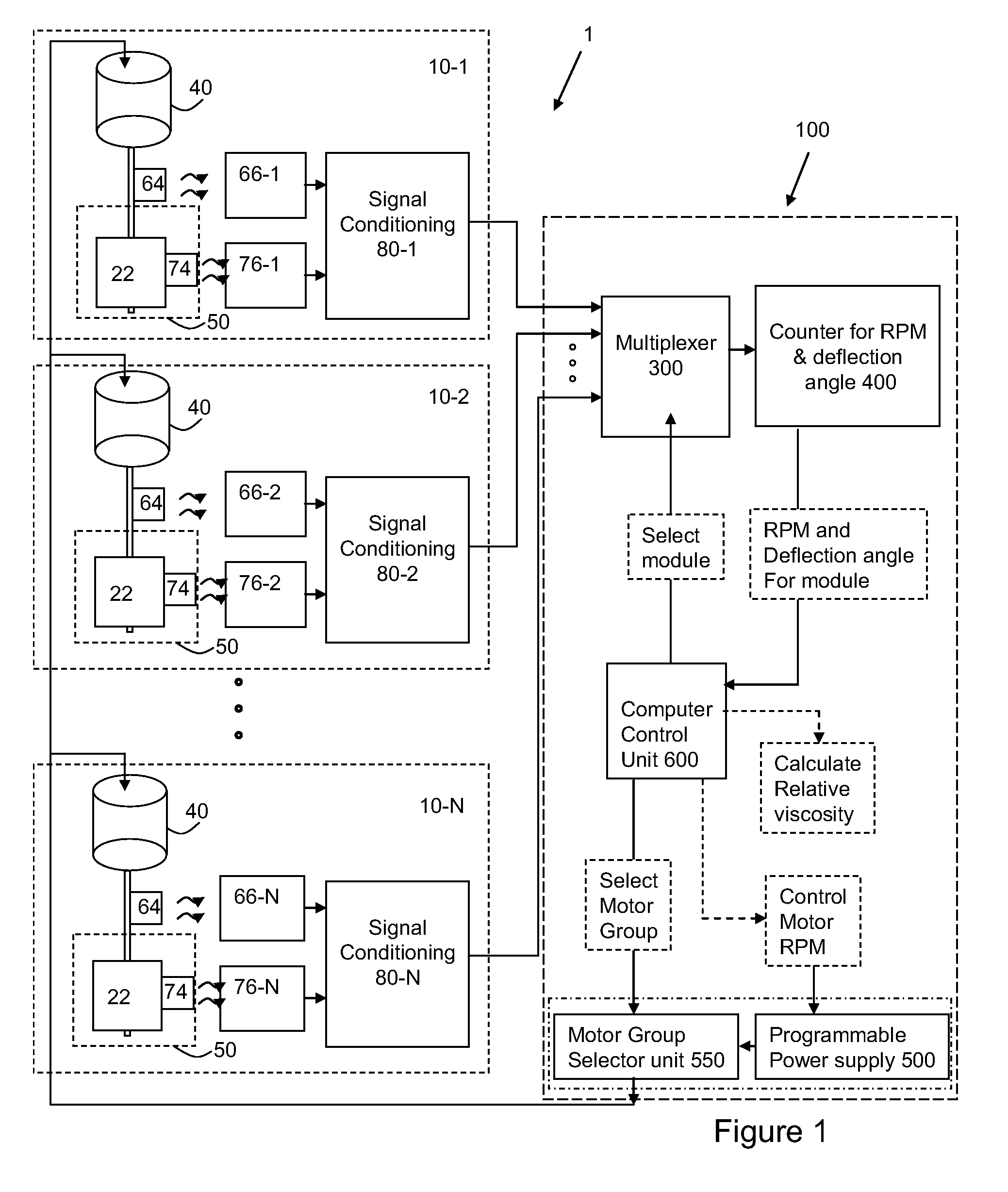
[0051]The apparatus and measurement method described above was used on a series of calibration fluids. These fluids were purchased from Brookfield viscosity standards available from Brookfield Engineering Laboratories, Inc, Middleboro, Mass., USA at the following viscosities: 1000 centipoise (cp), 300 cp, 100 cp, 75 cp, 56 cp and 1 cp. For a viscosity of zero, air was used. A fluid volume of 40 ml was placed in each vessel 50-1 through 50-6. The deflection angle of the paddle was measured for each fluid at three different shaft rotational speeds: 399, 225 and 166 revolutions per minute (RPM). The top plot of FIG. 7 shows these deflection angles plotted as a family of curves at each RPM. For example, for the 1000 cp fluid and at shaft speed of 399 RPM, the deflection angle of the paddle was just under 100 degrees from its equilibrium position. At 225 RPM, the paddle had a deflection angle of 58 degrees and at 166 RPM, the deflection angle was 43 degrees. The deflection angle was line...

example 2

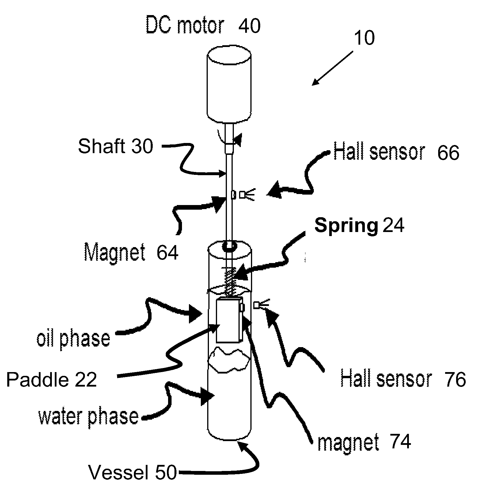
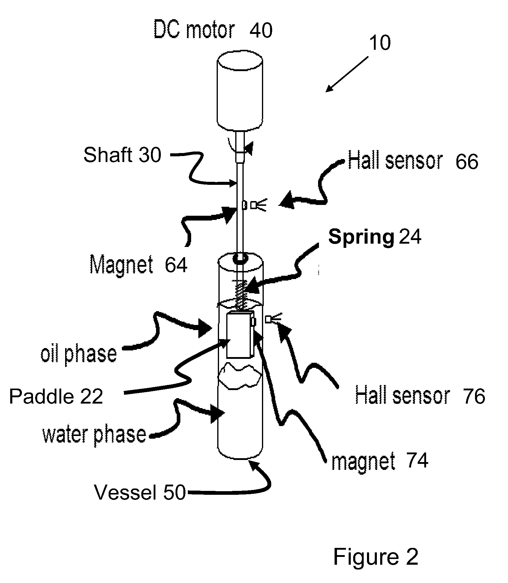
[0052]For this example, 40 ml of crude oil was placed in one vessel 50-1 of the apparatus. Approximately 14 ml of crude oil and 26 ml of water were placed in a second vessel 50-2. The relative viscosity of the oil phase of each vessel was measured at predetermined intervals for a full week. The relative viscosity was the relative change in the deflection angle of the paddle at a constant shaft speed. As shown in the plot of FIG. 8, there was essentially no change in the viscosity of the oil when either in contact with the water or not in contact with the water.

example 3

[0053]For this example, 14 ml of crude oil and 26 ml of water were placed in one vessel 50-1 of the apparatus. The same 14 ml of crude oil and 26 ml of water were placed in a second vessel 50-2. In this second vessel, 5 milliliters (ml) of an ATCC strain 33635, (Marinobacterium georgiense) at about 108 colony forming units per milliliter (cfu / ml) was used as an inoculum. The relative viscosity was measured each day as the relative change in the deflection angle at a constant RPM for a over a month. As shown in the plot of FIG. 9, there was a consistent increase in the viscosity of the oil for both the control as well as the inoculated well. This increase in viscosity was subsequently found to be due to evaporative loss of a small part of the oil since the head space in the vessel was vented into the nitrogen atmosphere chamber.


PUM

PropertyMeasurementUnit
volumesaaaaaaaaaa
lengthaaaaaaaaaa
diameteraaaaaaaaaa

Abstract

An apparatus for measuring in situ the viscosity of a fluid within a vessel which includes an impeller paddle immersed in the fluid rotated by an electric motor connected to a shaft passing through a wall of the vessel. The impeller paddle is connected to the shaft by a toroidal spring. The electric motor is controlled by a variable voltage power supply controlled by a computer. Sensors are mounted on the impeller paddle and the shaft to sense the rotational positions of each and to generate electronic signals indicative thereof. The electronic signals are processed by signal processing circuitry to determining the deflection angle of the impeller paddle and the results sent to a computer, where the signals are recorded and analyzed to determine the viscosity of the fluid.

Description

FIELD OF THE INVENTION[0001]The field of the invention is an apparatus to measure the viscosity of a fluid in-situ, such as in a sealed vessel or in a batch reactor or in a flow reactor. The fluid can be a single phase or multiphase fluid, such as a hydrocarbon compound and water in a bacterial enrichment culture.BACKGROUND OF THE INVENTION[0002]Certain anaerobic bacteria are known to have an ability to metabolize certain hydrocarbon molecules, such as those found in crude petroleum. The anaerobic bacteria break bonds in the hydrocarbon molecule, which results in a reduction of the viscosity of the crude petroleum. To evaluate the action of these anaerobic bacteria, samples of crude petroleum or petroleum and water mixtures are inoculated with anaerobic bacteria to create an enrichment culture and then tested under controlled temperature conditions over a period of time. Samples are removed periodically from the culture and tested to measure viscosity using prior art methods. This p...

Claims


Application Information

Patent Timeline
Patent Type & Authority Applications(United States)
IPC IPC(8): G01N11/14G01N11/00
CPCG01N11/14G01N33/483
Inventor ABBOTT, SCOT D.GROSKI, DAVID M.JACKSON, SCOTT CHRISTOPHER
Owner EI DU PONT DE NEMOURS & CO
Why Eureka
Try Eureka