Engine control system and method

a control system and engine technology, applied in the direction of electrical control, process and machine control, instruments, etc., can solve the problems of engine misfire, engine deterioration, engine emissions and combustion noise, etc., and achieve the effect of rapid, efficient and precise engine operation

Inactive Publication Date: 2010-05-13
DELPHI INT OPERATIONS LUXEMBOURG S A R L
View PDF17 Cites 48 Cited by
  • Summary
  • Abstract
  • Description
  • Claims
  • Application Information

AI Technical Summary

Benefits of technology

[0016]By measuring actual engine system parameters it is possible to correct the mo

Problems solved by technology

Electronic control may also control instability due to high pressure hydraulic oscillations generated by multiple injector activation.
As an example, it is noted that transient engine behaviour becomes very sensitive to multiple injection timings and quantities, and existing electronic control approaches lead to engine misfires.
The different fuel characteristics of such new fuels modify the manner in which combustion takes place and can lead to a deterioration in emission and combustion noise.
A limitation of the described control approach is the identification of a start of injection in a t

Method used


Image

  • Engine control system and method
  • Engine control system and method
  • Engine control system and method

Examples


Embodiment Construction

[0038]In the following description and associated drawings like numerals are used to denote like features.

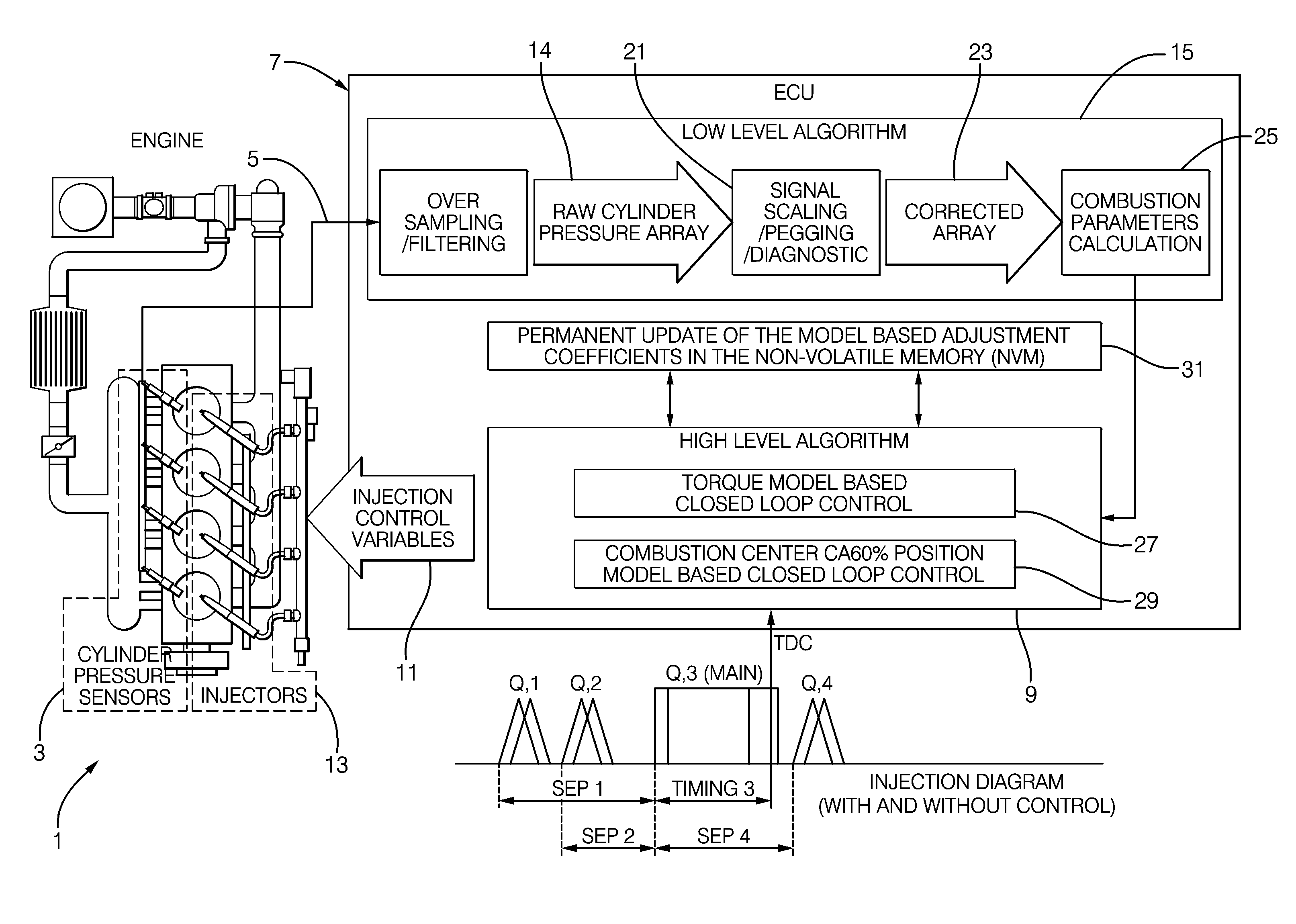
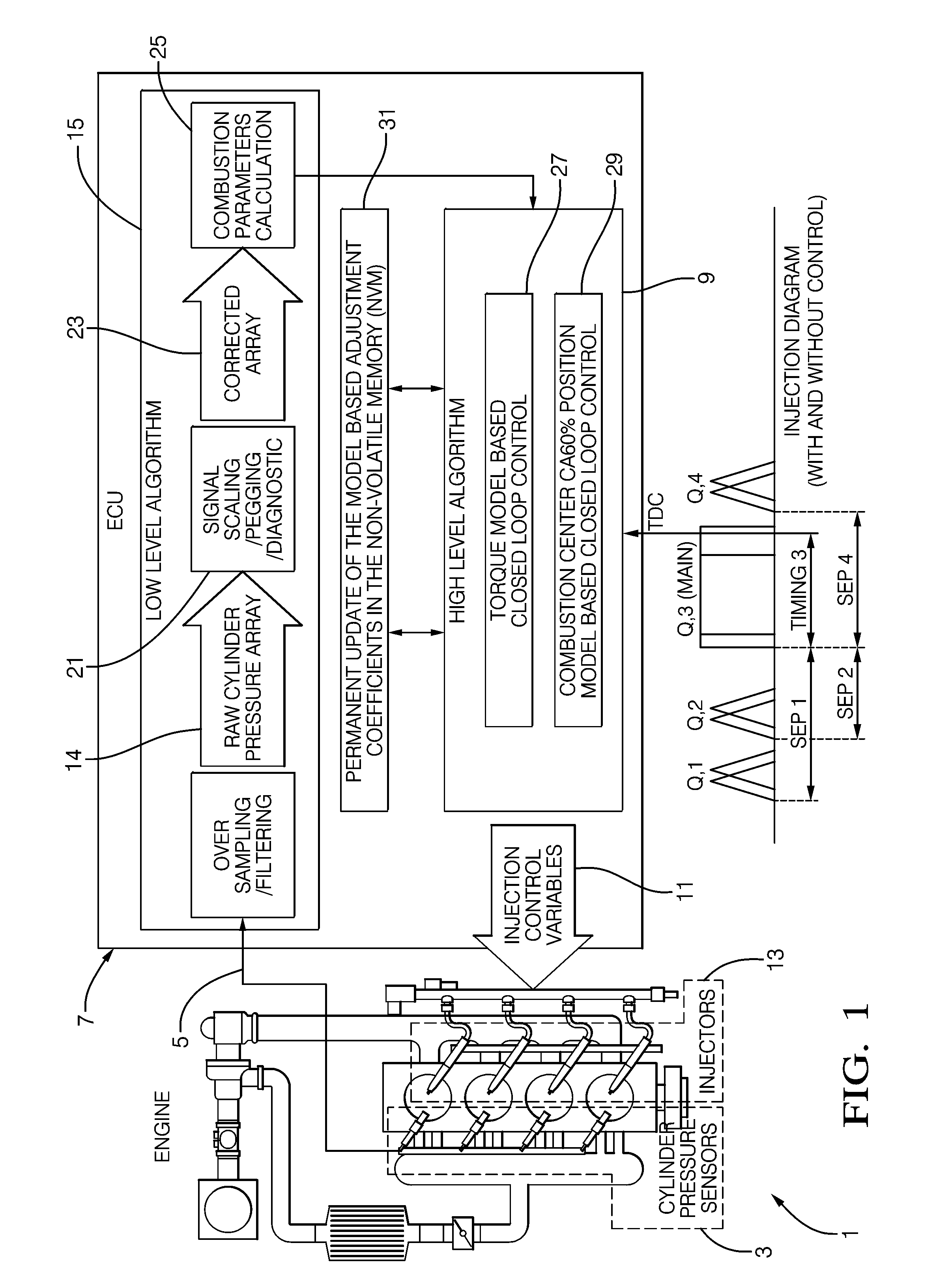
[0039]The following terms may also be referenced in the following description and associated drawings: IMEP—Indicated Mean Effective Pressure, used in this development for engine torque control (Bar) (Indicated engine torque=IMEP×Engine swept volume (constant)); SOC—Crank angle position at Start Of Combustion (Degree Crank Angle); CA50%—Crank angle position at 50% of cumulative heat release rate (here referred to as the Centre of Combustion Position) (Degree Crank Angle); SOI—Start of Injection (Degree Crank Angle); Prail—Rail pressure (Bar); η—Combustion efficiency; τ—Main injection timing (Degree Crank Angle); V—Cylinder volume (variable) (cm3); k—Compression Polytropic coefficient; Q—Fuel mass or generated combustion heat; TDC—Top Dead Centre (Reference 0 Crank angle); ECU Electronic Control unit.

[0040]FIG. 1 shows a representation of an engine system 1 in which in-cylinder p...


PUM


Abstract

A method of controlling an engine system, the method comprising: receiving data relating to engine operation; calculating in an engine model a combustion parameter and an injection parameter required to operate the engine system in accordance with the received engine data; controlling the engine system based on the calculated injection parameter wherein the method further comprises adjusting the engine model over time based on a comparison between the calculated engine combustion parameter and a corresponding measured engine combustion parameter

Description

TECHNICAL FIELD OF THE INVENTION[0001]The present invention relates to an engine control system and method. In particular, the present invention relates to the field of electronic systems and methods for the control of fuel injection quantity and injection timing.BACKGROUND TO THE INVENTION[0002]Engine development has seen improvements in many areas such as the reduction of engine emissions, reduction in fuel consumption and noise and increases in power density. Such improvements stem from improvements in engine design, fuel injection equipment, air management systems and aftertreatment.[0003]Advances in electronic control of engine systems have also been responsible in part for some of the above improvements and over the last ten years control strategies have been developed that allow precise control of engine torque and which allow for changes in the engine system due to mechanical wear to be compensated. Electronic control may also control instability due to high pressure hydraul...

Claims


Application Information

Patent Timeline
IPC IPC(8): F02M7/00F02D41/30
CPCF02D35/023F02D41/1406F02D41/2451F02D41/2477F02D41/40F02D2041/1416Y02T10/44F02D41/028Y02T10/40
Inventor GUERRASSI, NOUREDDINEALLEZY, PIERRE
Owner DELPHI INT OPERATIONS LUXEMBOURG S A R L
Why Eureka
Try Eureka