
Mass spectrometer

a mass spectrometer and mass spectrometer technology, applied in the field of mass spectrometers, can solve the problems of limited performance improvement based on a conventional multipole rod type configuration, difficulty in increasing detection sensitivity and accuracy, and small flexibility in parameter selection, so as to improve the ion beam's convergence and the effect of improving the ion beam acceptance and high beam convergen

Inactive Publication Date: 2010-05-13
SHIMADZU CORP
View PDF6 Cites 8 Cited by
  • Summary
  • Abstract
  • Description
  • Claims
  • Application Information

AI Technical Summary

Benefits of technology

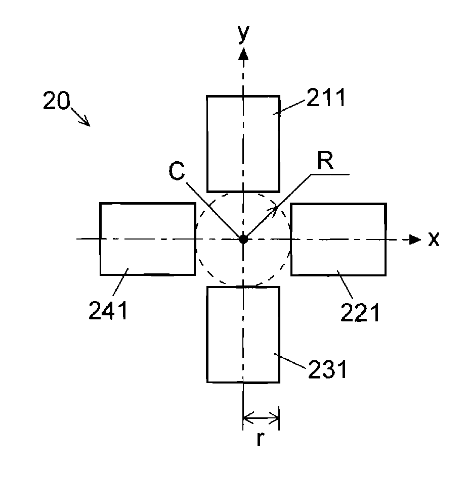
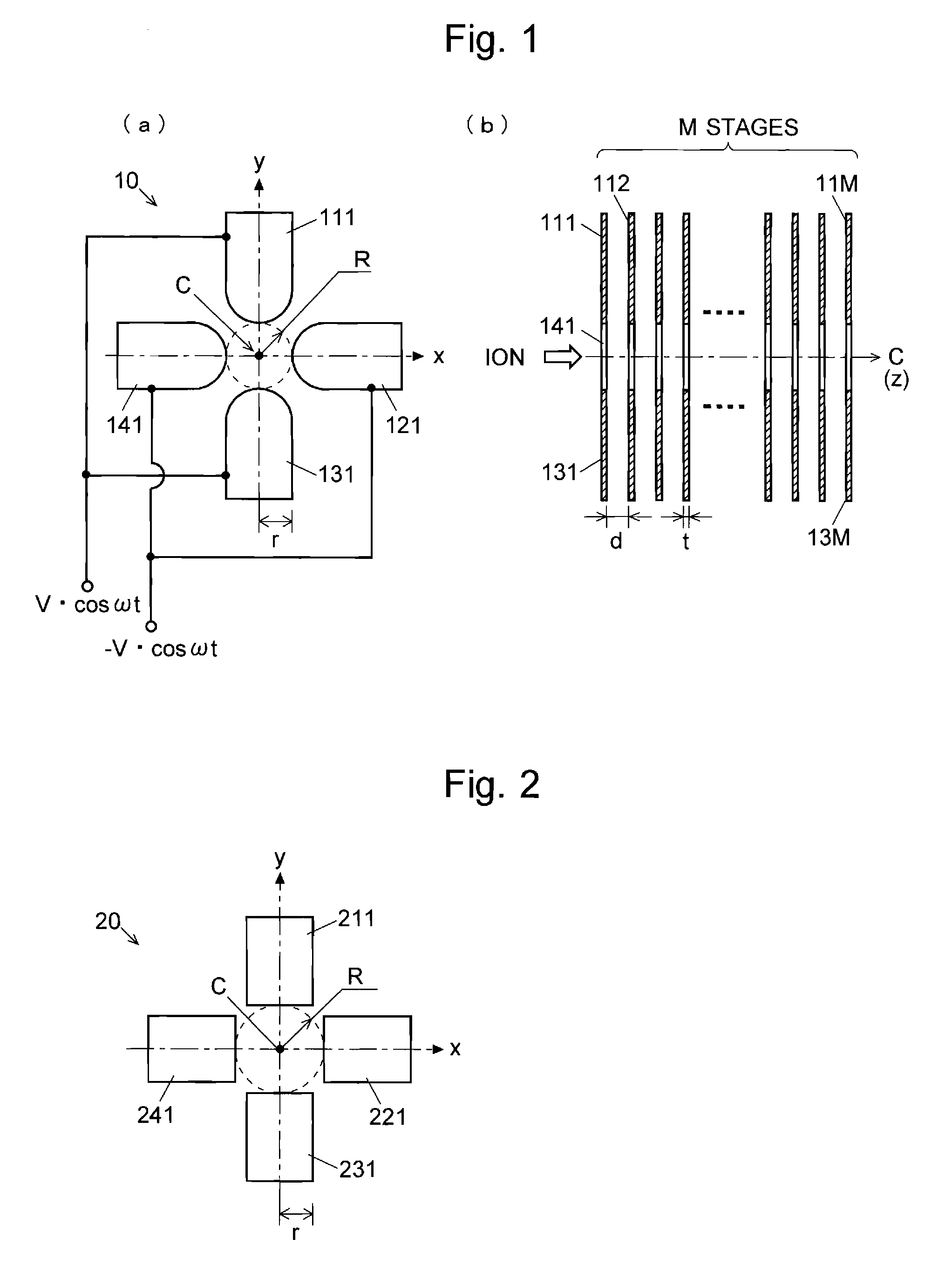
[0023]According to the aforementioned analysis by the inventors of the present invention, in the case where the plate thickness of the electrode plain plates is the same, as the interval between the adjacent electrode plain plates becomes larger, the quadrupole field components become smaller and the higher-order multipole field components increase. In the case where the intervals between the adjacent electrode plain plates are the same, as the plate thickness of the electrode plain plates becomes thicker, the quadrupole field components increase. The larger the quadrupole field components are, the better the ion beam's convergence is. Therefore it is preferable that the quadrupole field components increase in the region where the ion's convergence is significant, or normally in the region adjacent to the ion exit side for sending ions into the subsequent stage, in an ion transport optical system. On the other hand, the larger the multipole field components whose order is higher than quadrupole are, the better the ion acceptance is. Therefore, it is preferable that high-order multipole field components increase in the region where the ion acceptance is significant, or normally in the region adjacent to the ion injection side for receiving ions coming from the previous stage, in an ion transport optical system.
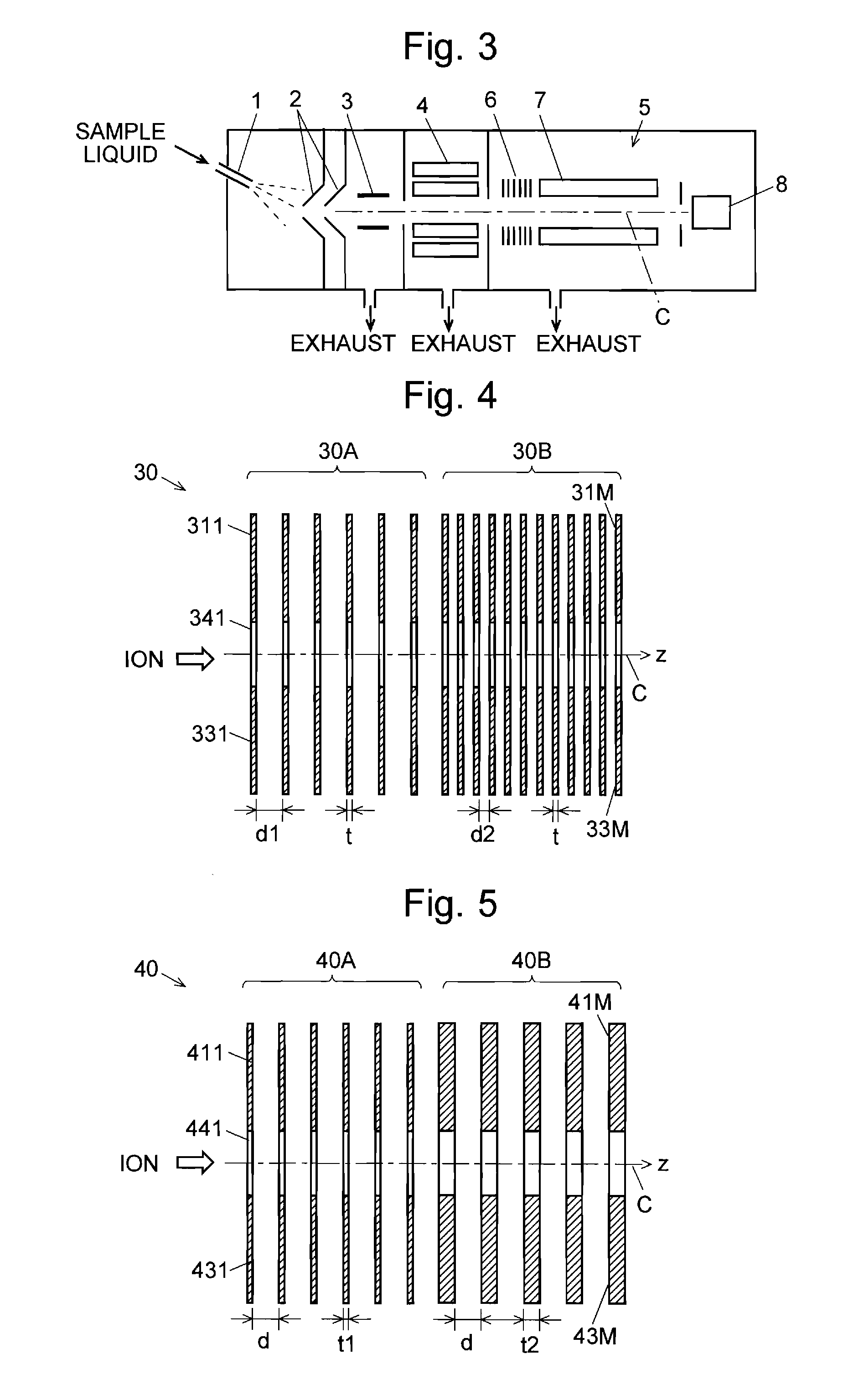
[0024]Given these factors, as a preferable embodiment of the first aspect of the present invention, in the virtual multipole rod type ion transport optical system, the interval between adjacent electrode plain plates may be relatively large in the ion injection side and the interval between adjacent electrode plain plates may be relatively small at the ion exit side.
[0025]As a preferable embodiment of the second aspect of the present invention, in the virtual multipole rod type ion transport optical system, a relatively thin electrode plain plate or plates may be placed at the ion injection side and a relatively thick electrode plain plate or plates may be placed at the ion exit side.
[0026]With the configuration according to these embodiments, ions coming from the previous stage are effectively taken by a high acceptance into the virtual multipole rod type ion transport optical system, and are sent into the subsequent stage in the state converged in the vicinity of the ion optical axis by a high beam convergence. Therefore, in this virtual multipole rod type ion transport optical system, ions coming from the component in the previous stage are efficiently taken and the ions are efficiently introduced into the subsequent component. Accordingly, more ions than ever before can be mass analyzed and the analysis' high sensitivity and high accuracy can be achieved.
[0027]In a liquid chromatograph mass spectrometer for example, a multistage differential pumping system is often used in order to keep the inside of the analysis chamber in a high vacuum state, where a mass separator and ion detector are provided. In such a configuration, an aperture which communicates the chambers with different gas pressure is extremely small. The ion transport optical system having a high ion convergence at the ion exit side as previously described is particularly advantageous in sending ions into the subsequent stage through such an extremely small aperture.
[0028]Contrary to the aforementioned embodiment, the interval between adjacent electrode plain plates may be relatively small at the ion injection side and the interval between adjacent electrode plain plates may be relatively large at the ion exit side. Simultaneously or alternatively, a relatively thick electrode plain plate or plates may be placed at the ion entrance side, and a relatively thin electrode plain plate or plates may be placed at the ion exit side. In these cases, ions which are converged in the anterior half section can be sent into the subsequent stage with high passage efficiency. In addition, the interval between adjacent electrode plain plates and the thickness of each electrode plain plate may be changed among the ion injection side, ion exit side, and their intermediate section. With such a configuration, for example, a function of temporarily storing ions in the vicinity of the intermediate portion of the ion transport optical system, i.e. a function similar to an ion trap, can be realized.

Problems solved by technology

However, the conventional type ion transport optical system has a disadvantage in that the flexibility of the selection of parameters is little and therefore an ion transport optical system having optimal ion optical properties suitable for the purpose cannot be always used, which may lead to the difficulty in increasing the detection sensitivity and accuracy.
However, in practice, the performance improvement based on a conventional multipole rod type configuration has limitations for the aforementioned reasons.

Method used


Image

  • Mass spectrometer
  • Mass spectrometer
  • Mass spectrometer

Examples


embodiments

[0079]Next, a mass spectrometer which is an embodiment of the mass spectrometer according to the present invention will be described with reference to the figures. FIG. 3 is a configuration diagram of the main portion of the mass spectrometer of the present embodiment.

[0080]This mass spectrometer is an atmospheric pressure ionization mass spectrometer in which an electrospray ion source is used as an ion source. A liquid chromatograph is provided in the previous stage, and a sample liquid whose components have been separated in the column of the liquid chromatograph is introduced into a nozzle 1. The sample liquid is supplied with biased charges from the nozzle 1 and eventually atomized (or electro sprayed) into a space at substantially atmospheric pressure. When the solvent contained in the droplets of the sprayed liquid vaporizes, a variety of components included in the sample are ionized and sent into the subsequent stage through a sampling cone 2. These ions are converged, and a...


PUM


Abstract

One virtual rod electrode is composed by a plurality of electrode plain plates arranged in the ion optical axis direction, and four virtual rod electrodes are arranged around the ion optical axis to form a virtual quadrupole rod type ion transport optical system (30). In one virtual rod electrode, the interval between the adjacent electrode plain plates is set to be large in the anterior area (30A) and small in the posterior area (30B). As the interval between electrodes becomes larger, high-order multipole field components increase and therefore the ion acceptance is increased, which enables an efficient acceptance of ions coming from the previous stage. On the other hand, if the interval between electrodes is small, the quadrupole field components relatively increase and the ion beam's convergence is improved. Therefore, ions can be effectively introduced into a quadrupole mass filter for example in the subsequent stage, which contributes to the enhancement of the mass analysis' sensitivity and accuracy.

Description

TECHNICAL FIELD[0001]The present invention relates to a mass spectrometer used in a liquid chromatograph mass spectrometer, gas chromatograph mass spectrometer, and other mass spectrometers. More precisely, it relates to an ion transport optical system for transporting an ion or ions into the subsequent stage in a mass spectrometer.BACKGROUND ART[0002]In a mass spectrometer, an ion transport optical system, which is called an ion lens or ion guide, is used to converge ions sent from the previous stage, and in some cases accelerate them, in order to send them to a mass analyzer such as a quadrupole mass filter in the subsequent stage. One type of such ion transport optical system conventionally used is a multipole rod type, such as a quadrupole or octapole system. In a quadrupole mass filter which is often used as a mass analyzer for separating ions in accordance with their mass-to-charge ratio, a pre-filter (which is also called pre-rods) composed of short quadrupole rod electrodes ...

Claims


Application Information

Patent Timeline
Patent Type & Authority Applications(United States)
IPC IPC(8): H01J49/00
CPCH01J49/004H01J49/063H01J49/065H01J49/4235
Inventor NISHIGUCHI, MASARUUENO, YOSHIHIROOKUMURA, DAISUKEITOI, HIROTO
Owner SHIMADZU CORP
Learn More