
Electronic current interrupt device for battery

a technology of electronic current interrupt and battery, which is applied in the direction of batteries, cell components, safety/protection circuits, etc., can solve the problems of lithium cells easily being subject to damage, lithium cells easily being subject to explosion,

Inactive Publication Date: 2010-05-13
LEYDEN ENERGY
View PDF7 Cites 108 Cited by
  • Summary
  • Abstract
  • Description
  • Claims
  • Application Information

AI Technical Summary

Benefits of technology

[0062]The flexible carbon sheeting, such as carbon nanotubes or graphite sheet for the practice of the present invention provides particular advantages in achieving low contact resistance. By virtue of its high ductility, conformability, and toughness it can be made to form particularly intimate and therefore low resistance contacts with electrode structures that may intentionally or unintentionally proffer an uneven contact surface. In any event, in the practice of the present invention, the contact resistance between the positive electrode and the graphite current collector of the present invention preferably does not exceed 50 ohm-cm2, in one instance, does not exceed 10 ohms-cm2, and in another instance, does not exceed 2 ohms-cm2. Contact resistance can be determined by any convenient method as known to one of ordinary skill in the art. Simple measurement with an ohm-meter is possible.

Problems solved by technology

Lithium based cells are easily subject to damage when they are over-discharged, run away temperature or in short circuit conditions.
Over-temperature may also cause explosion of the lithium based cells, especially when a number of lithium cells are connected in series and / or in parallel to form a battery assembly to effect high current charging and discharging for devices that require much larger output power than a single cell can provide.
In such applications, the lithium cells are easily subject to damage caused by over-discharging and the costs are much higher when the batteries are so damaged.
Also, explosion of the batteries is more powerful, if it happens.
Any possible short circuit condition is particularly hazardous.
A typical lithium ion cell can produce as much 30 amps on a short circuit condition and this can destroy the entire battery.
Indirectly high temperature can lead to electrolyte decomposition, gas generation and increased internal cell pressure.
The movement of the vent disc breaks a weld and disconnects the positive header of the cell from the positive electrode, thus permanently interrupting the flow of current in or out of the cell.
This high temperature can result from either an over current through the resistive PTC device or high internal or external temperatures.
The PTC device does not totally eliminate the current into or out of the cell; the current is decreased.
The major drawback to the PTC device is that its impedance is a significant contribution to the total impedance of the cell.
Also, in no way can the CID or PTC devices activate based on absolute temperature or the rate of change of temperature as a function of time.

Method used


Image

  • Electronic current interrupt device for battery
  • Electronic current interrupt device for battery
  • Electronic current interrupt device for battery

Examples


Embodiment Construction

[0010]The following descriptions are of exemplary embodiments only, and are not intended to limit the scope, applicability or configuration of the invention in any way. Rather, the following description provides a convenient illustration for implementing exemplary embodiments of the invention. Various changes to the described embodiments may be made in the function and arrangement of the elements described without departing from the scope of the invention as set forth in the appended claims.

[0011]Preferred embodiments of the invention are described in detail below. Referring to the drawings, like numbers indicate like parts. As used in the description herein and throughout the claims, the following terms take the meanings explicitly associated herein, unless the context clearly dictates otherwise: the meaning of “a,”“an,” and “the” includes plural reference.

[0012]The term “alkyl”, by itself or as part of another substituent, includes, unless otherwise stated, a straight or branched ...


PUM


Abstract

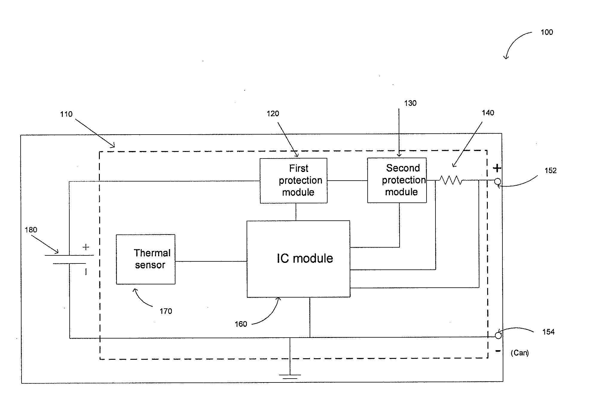
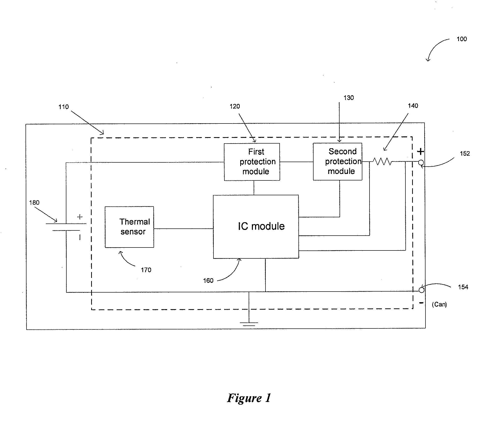
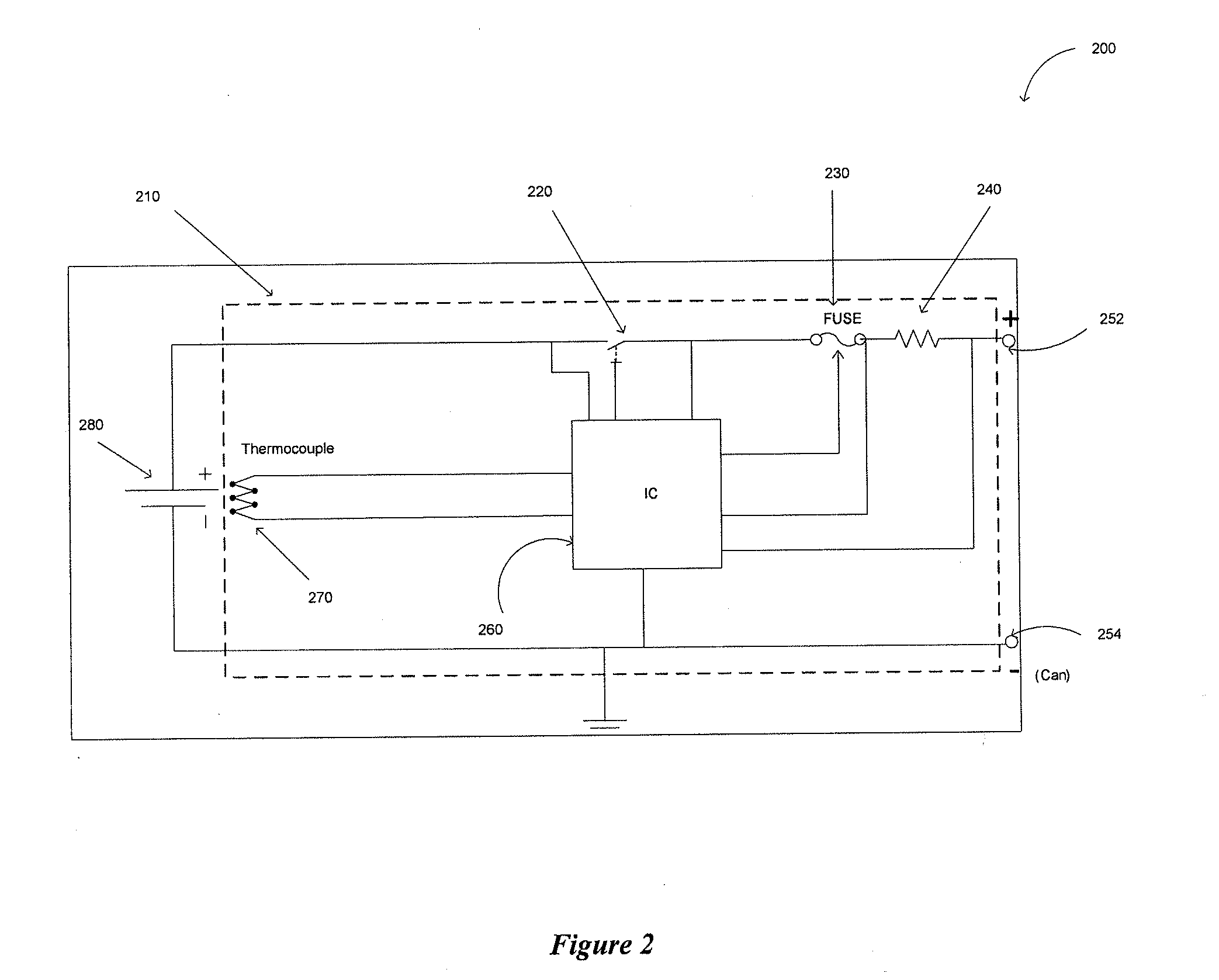
The present invention provides a protection circuit disposed in a lithium-ion cell for protection of the lithium-ion cell. The protection circuit includes a first protection module, a second protection module, an integrated circuit module, a thermal sensor or thermocouple, a switch, a fuse and / or a resistor.

Description

CROSS-REFERENCES TO RELATED APPLICATIONS[0001]This application claims priority to U.S. Provisional Patent Application No. 61 / 102,323 filed Oct. 2, 2008, which application is incorporated herein by reference in its entirety and for all purposes.BACKGROUND OF THE INVENTION[0002]Lithium based cells are easily subject to damage when they are over-discharged, run away temperature or in short circuit conditions. Over-temperature may also cause explosion of the lithium based cells, especially when a number of lithium cells are connected in series and / or in parallel to form a battery assembly to effect high current charging and discharging for devices that require much larger output power than a single cell can provide. In such applications, the lithium cells are easily subject to damage caused by over-discharging and the costs are much higher when the batteries are so damaged. Also, explosion of the batteries is more powerful, if it happens. Any possible short circuit condition is particul...

Claims


Application Information

Patent Timeline
IPC IPC(8): H01M14/00H01M50/569H01M50/574H01M50/583
CPCH01M2/34H01M2/348H01M10/0525H01M10/425Y02E60/122H01M10/486H01M2200/103H01M2200/106H02J7/0031H01M10/48H02J7/0029Y02E60/10H01M50/581H01M50/583H01M50/574H01M50/569H02H7/18H01M10/44H02J7/04G01R31/36
Inventor PATEL, AAKARJUZKOW, MARC
Owner LEYDEN ENERGY
Learn More