Suture anchoring system and method

a suture and anchoring technology, applied in the field of suture anchoring systems and methods, can solve the problems of affecting shoulder movement, affecting the normal function of the ligament, and being relatively weak, and achieve the effect of weakening the bony bridg

Inactive Publication Date: 2010-05-13
PANDYA RAJIV D
View PDF37 Cites 33 Cited by
  • Summary
  • Abstract
  • Description
  • Claims
  • Application Information

AI Technical Summary

Benefits of technology

[0031]The present invention involves both methodology and tools necessary to allow for the creation of angled tunnels, including the blind creation of angled osteal tunnels, and the intraosseous retrieval of sutures from osteal tunnels. This entails the use of an intraosseous guide, a feeder and retrieval system. The resultant tunnels provide robust bony bridges even with minimal distance between the surface points of entry and exit on the bone, can be created through

Problems solved by technology

Otherwise, the ligament will eventually be too loose or too tight for normal function.
Movement of the shoulder may be impaired if the axillary nerve is damaged.
Often, this results in a tunnel being close to the surface of the bone, which tunnel may have a thin wall and therefore be relatively weak and subject to breaking.
Further, while it may be desirable for surgeons to employ their discretion in selecting the entrance site of the osteal tunnel, limitations in visibility and accuracy considerations dictate that surgical positioning instruments are needed to ensure that an osteal tunnel has a precise drill exit point.
Often, surgeons are required to work in an area that is “boxed in” by nerves, which gives rise to a need for surgeons to forego the use of conventional surgical positioning instruments that might interfere with these delicate areas.
There are several limitations to current techniques of fixing soft tissue to bone.
The latter carries the risk of implant complications including infection and bony osteolysis in addition to failure of fixation.
However, these techniques are limited by technical constraints including the

Method used


Image

  • Suture anchoring system and method
  • Suture anchoring system and method
  • Suture anchoring system and method

Examples


Embodiment Construction

[0060]The following detailed description of preferred embodiments is presented only for illustrative and descriptive purposes and is not intended to be exhaustive or to limit the scope and spirit of the invention. The embodiments were selected and described to best explain the principles of the invention and its practical applications. One of ordinary skill in the art will recognize that many variations can be made to the invention disclosed in this specification without departing from the scope and spirit of the invention.

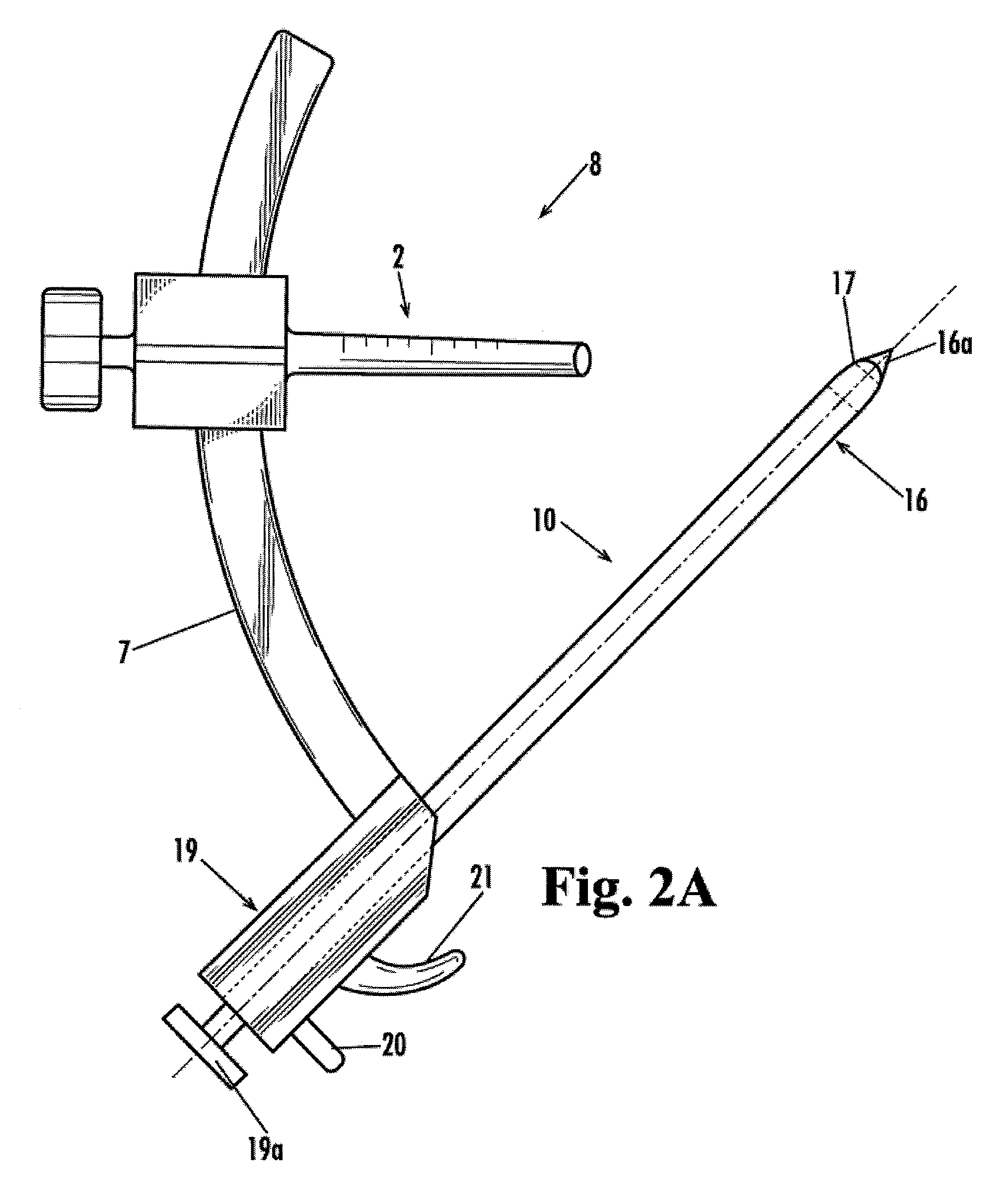
[0061]Illustrative embodiments of a device and method for drilling angled osteal tunnels and anchoring sutures therein according to the present invention are shown in FIGS. 2A through 9. FIG. 2A is an elevation view of an embodiment of the present invention having a movable drill guide. FIG. 2B is a top plan view of the present invention shown in FIG. 2A, further showing the attachment of the drill guide. FIG. 2C is bottom plan view of an embodiment of the guide c...


PUM


Abstract

A suture anchoring system having an anchor structure through which at least one suture can extend, the anchor being compressible or deformable to anchor the suture, and a method for using the suture anchoring system by attaching one end of a suture to a muscle, ligament or bone; threading the suture through an osteal tunnel; providing a surgical anchor comprising a cuff of deformable material suitably shaped to receive a suture, wherein said cuff, when compressed, tightly grips a suture and forms a point of support, whereby said deformed anchor prevents a suture from being pulled through a drilled osteal tunnel; threading the other end of the suture through the anchor; and deforming said anchor tightly about the suture to form a point of support.

Description

BACKGROUND OF THE INVENTION[0001]1. Technical Field[0002]The present invention generally is related to the field of osteal guides, surgical drilling systems and methods and devices for drilling osteal tunnels, and more particularly is related to systems and methods for anchoring sutures, such as sutures extending through osteal tunnels.[0003]2. Related Art[0004]The anterior and posterior cruciate ligaments in the knee assist in providing stability to the function of the knee. The cruciate ligaments control gliding, sliding, and rotation of the knee. To accomplish this, the anterior and posterior cruciate ligaments function according to the principles of a crossed four bar linkage, which is closely related to and dependent upon the bony constraints of the surrounding bones. Thus, the anatomic origin and insertion of both of the ligaments is crucial. Often the anterior cruciate ligament (ACL) becomes ruptured or torn, requiring replacement and reconstruction of the ligament in order t...

Claims


Application Information

Patent Timeline
IPC IPC(8): A61B17/04A61B19/00
CPCA61B17/04A61B17/0482A61B17/0483A61B2017/1778A61B2017/0454A61B17/1684A61B17/1714A61B17/1778
Inventor PANDYA, RAJIV D.
Owner PANDYA RAJIV D
Why Eureka
Try Eureka