

Exhaust purification control device and exhaust purification system of internal combustion engine
- Summary
- Abstract
- Description
- Claims
- Application Information
AI Technical Summary
Benefits of technology
Problems solved by technology
Method used
Image

Examples
first embodiment
[0046]Hereafter, an exhaust purification control device of an internal combustion engine according to a first embodiment of the present invention will be explained with reference to the drawings.
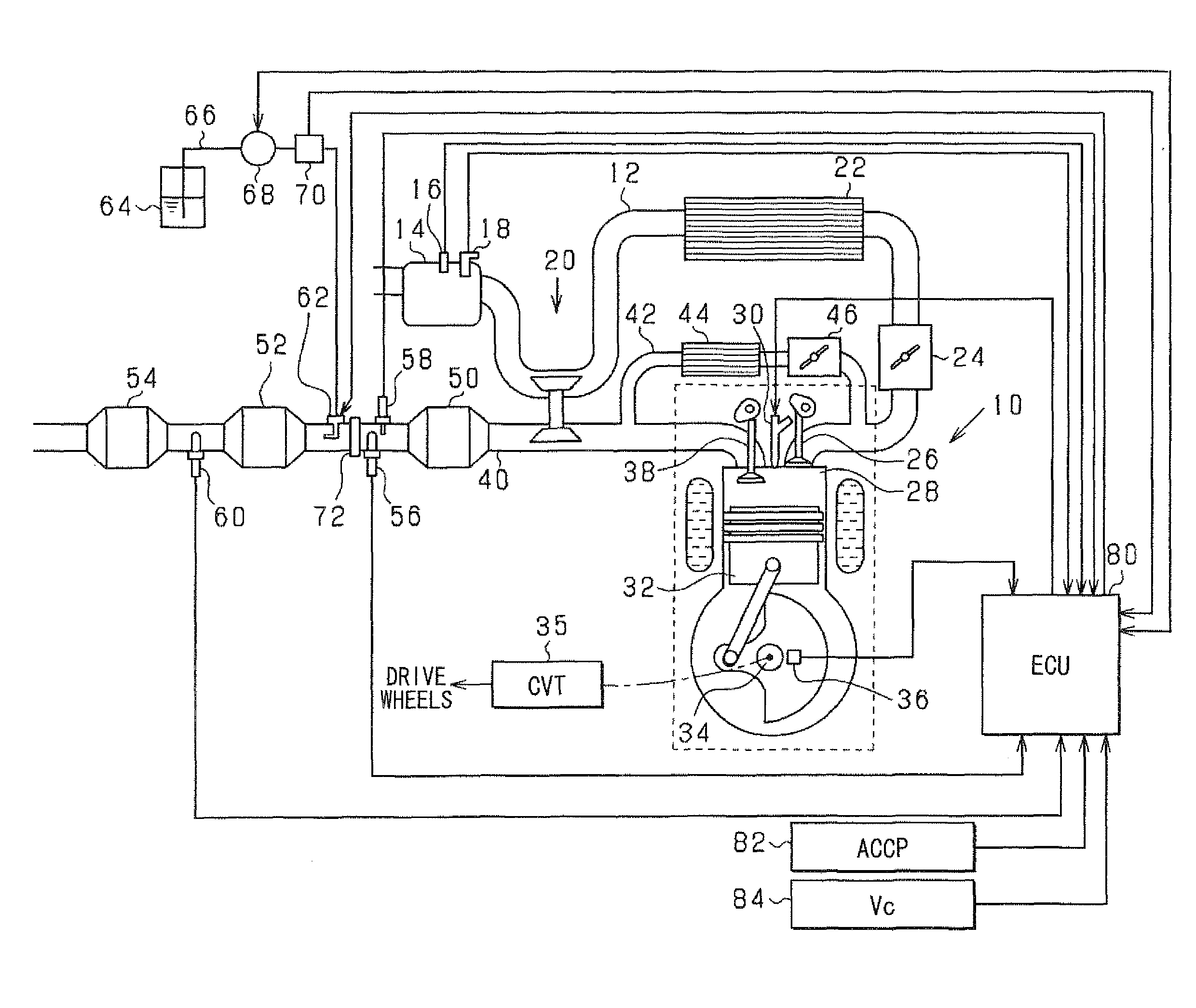
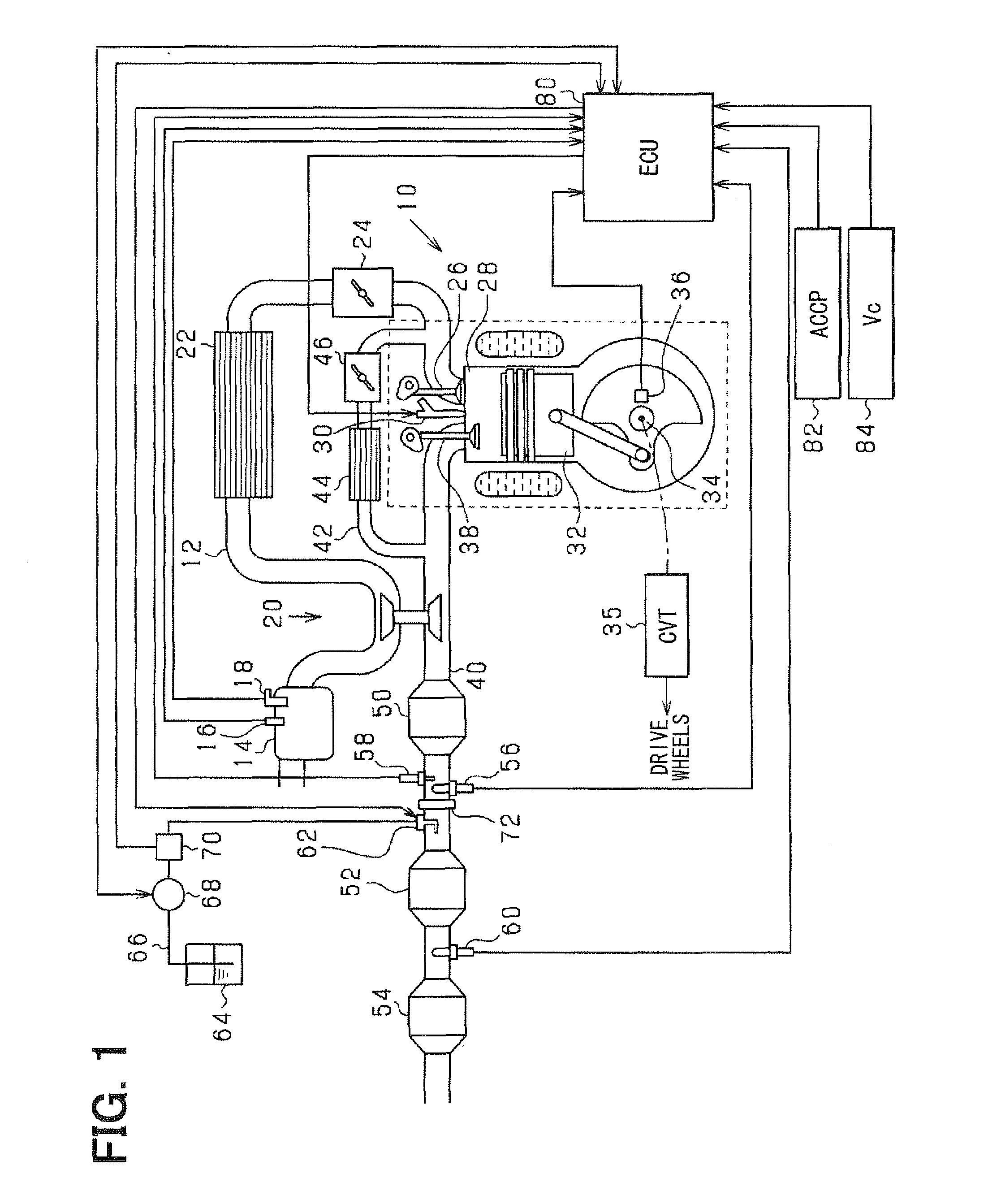
[0047]A diesel engine 10 is an internal combustion engine having a reciprocating engine structure. An air cleaner 14 is provided upstream of an intake passage 12 of the diesel engine 10. An intake temperature sensor 16 for sensing intake air temperature and an airflow meter 18 for sensing an intake air flow rate are provided to the air cleaner 14. A turbocharger 20 is provided downstream of the air cleaner 14. An air supercharged by the turbocharger 20 is cooled by an intercooler 22 and then supplied to a downstream side of the intake passage 12. The air is supplied to a combustion chamber 28 of the diesel engine 10 through a throttle valve 24, which adjusts a flow passage area of the intake passage 12, and an intake valve 26, which opens and closes communication between the combustion chamb...
second embodiment
[0095]Next, a second embodiment of the present invention will be described with reference to the drawings, focusing on the differences from the first embodiment.
[0096]In the present embodiment, the addition quantity of the urea solution added by the urea solution addition valve 62 is calculated based on the NOx purification rate Rnox. The NOx purification rate Rnox is calculated based on the both sensing values of the upstream NOx sensor 56 and the downstream NOx sensor 60.
[0097]FIG. 8 shows a procedure of purification processing of the nitrogen oxides according to the present embodiment. The ECU 80 repeatedly performs the processing, for example, in a predetermined cycle. Processing in FIG. 8 corresponding to the processing in FIG. 7 is indicated with the same step number as in FIG. 7.
[0098]As shown in FIG. 8, in the present embodiment, as the execution condition of the decrease control of the urea solution addition quantity Qur in the case where the idling is not performed present...
PUM
 Abstract
Description
Claims
Application Information