High-strength martensite heat resisting cast steel, method of producing the steel, and applications of the steel

Inactive Publication Date: 2010-05-20
HITACHI LTD
View PDF3 Cites 6 Cited by
  • Summary
  • Abstract
  • Description
  • Claims
  • Application Information

AI Technical Summary

Benefits of technology

[0006]An object of the present invention is to provide a high-strength martensite heat resisting steel which has long-time creep rupture strength required for steam temperature condition of 600-630° C. and toughness at room temperature, and which is suitable for use as a material of a steam turbine rotor shaft and as large-sized forged steel with an improvement of hot forgeability, and to a method of producing that steel. Another object of the present invention is to provide a steam turbine rotor shaft and a method of producing it, a steam turbine rotor blade and a method of producing it, a steam turbine stator nozzle and a method of producing it, as well as a steam turbine and a steam turbine power plant, including the method of producing the steam turbine, in which the turbine blade in a stage using steam to cool the rotor has a larger height by increasing the high-temperature tensile strength, and higher thermal efficiency is ensured.

Problems solved by technology

If the toughness at room temperature is low, there is a risk that the rotor shaft may cause brittle rupture at the start of the steam turbine.
Meanwhile, steam turbines have recently been improved with intent to realize higher efficiency and larger capacity, but a thermal power plant operating at steam temperature of 650° C. is not yet realized.
The reasons reside in not only the state of the art that the high-temperature material technology for the entire plant is still insufficient, but also the problem of reduction in the material cost which is necessitated from a market trend toward a lower cost.
The above-described materials of the turbine rotor shaft adapted for steam temperature of 600° C. or above are relatively high in cost.
A primary one of factors pushing up the cost is poor productivity.
In producing a large-sized forged product, however, B noticeably reduces productivity because of increasing forging resistance and narrowing a forgeable temperature range.
Thus, the production cost is increased.

Method used


Image

  • High-strength martensite heat resisting cast steel, method of producing the steel, and applications of the steel
  • High-strength martensite heat resisting cast steel, method of producing the steel, and applications of the steel
  • High-strength martensite heat resisting cast steel, method of producing the steel, and applications of the steel

Examples


first embodiment

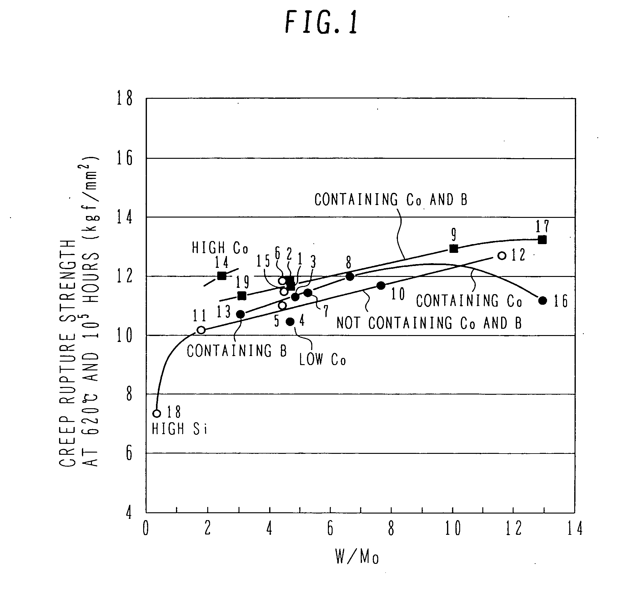
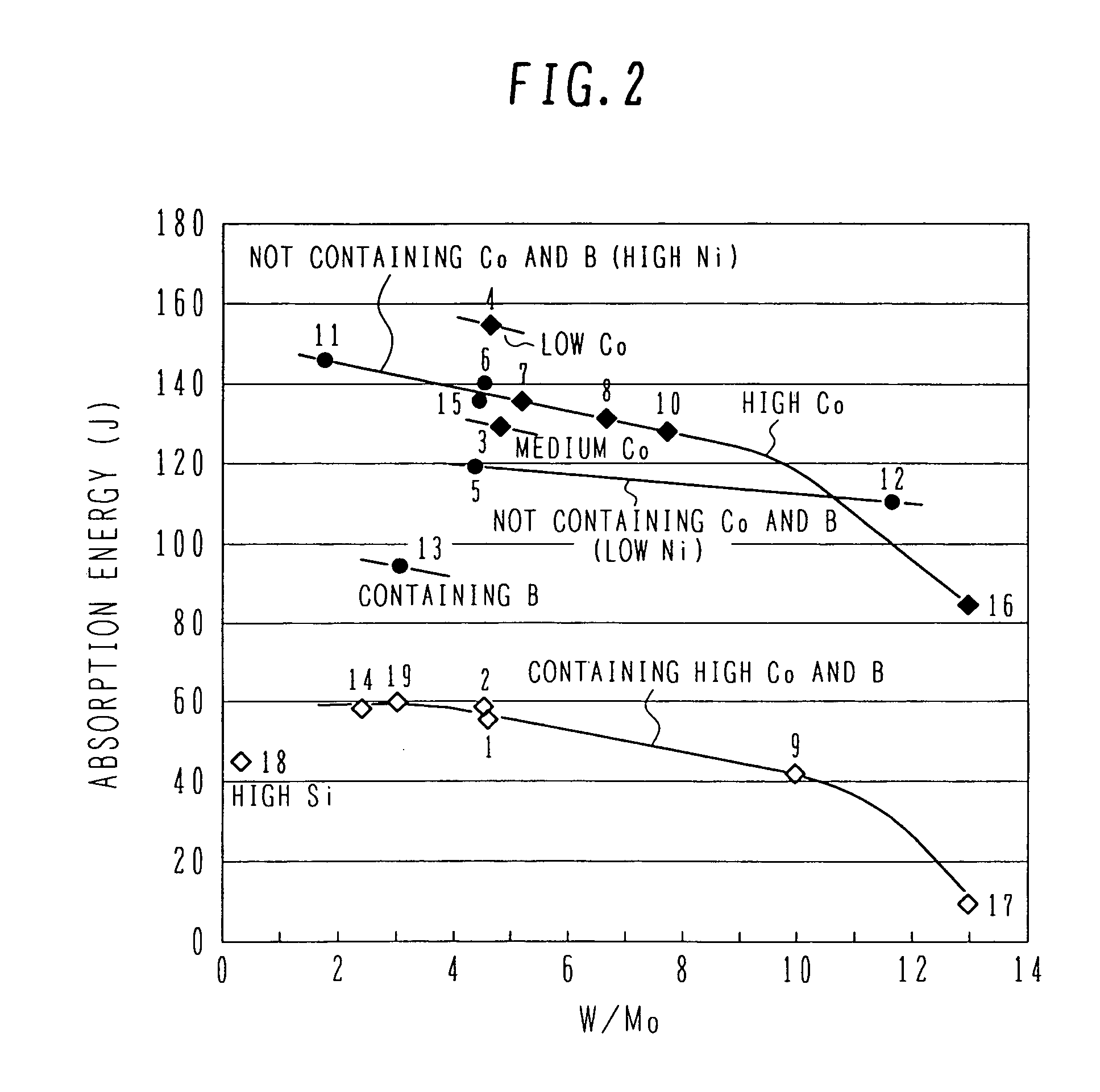
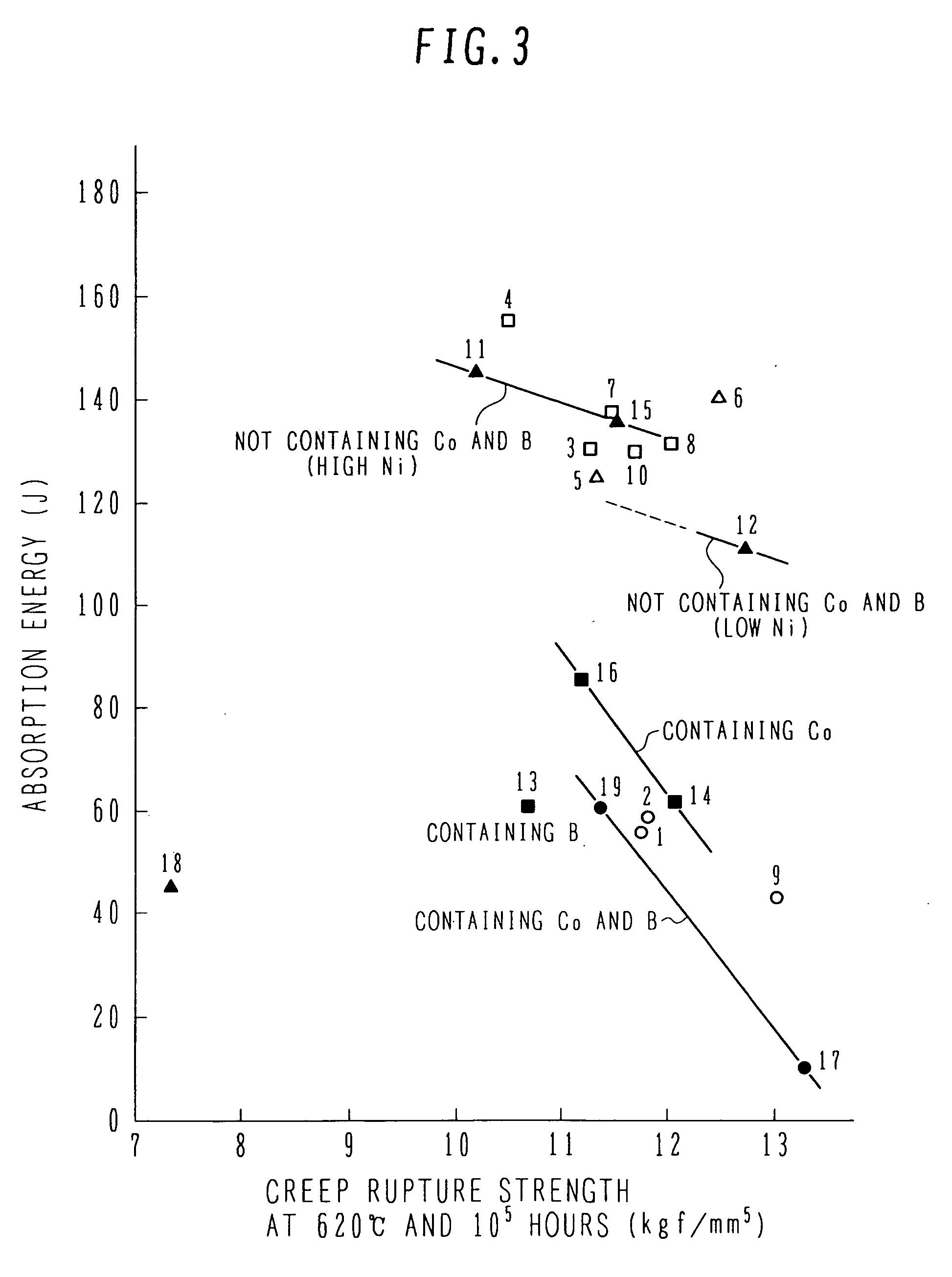
[0050]Table 1, given below, shows chemical composition (% by mass) of the steel of the present invention and comparative steels which are used in this embodiment for comparative studies. In Table 1, samples No. 1-10 represent the steel of the present invention, samples No. 11-13 represent the comparative steels, and samples No. 14-19 represent the known steels (corresponding to Patent Documents 1 and 3). As seen from Table 1, in the samples No. 1-10 representing the steel of the present invention, the (W / Mo) ratio is 4.0-10.0.

[0051]Each of the steel samples shown in Table 1 was prepared by producing an ingot of 50 kg in a vacuum high-frequency induction melting furnace, and forming a plate of 30 mm (t)×90 mm (w)×L by hot forging. The hot forging was performed under heating conditions of temperature 1150° C.×3 hours and at the forging temperature of 1150-950° C. while the heating was repeated six times.

[0052]Simulating a central portion of a large-sized steam turbine rotor shaft, hea...

second embodiment

[0061]FIG. 4 is a cross-sectional view of a high-pressure steam turbine (HP) using the high-strength martensite heat resisting steel according to the present invention as a rotor shaft material. FIG. 5 is a cross-sectional view of an intermediate-pressure steam turbine (IP) using the high-strength martensite heat resisting steel according to the present invention as a rotor shaft material. In this second embodiment, the HP and the IP are connected in tandem to constitute a steam turbine power plant having steam temperature of 625° C. and output capacity of 1050 MW. A low-pressure steam turbine is of the cross-compound four-flow exhaust type, and the blade height in the last stage thereof is 43 inches. More specifically, the steam turbine power plant can be constituted by a set of (HP)-(IP)-generator and a set of two low-pressure steam turbines (LP)-generator, each set operating at the rotation speed of 3000 rpm, or by a set of (HP)-(LP)-generator and a set of (IP)-(LP)-generator, ea...

third embodiment

[0080]FIG. 6 is a cross-sectional view of a high- and intermediate-pressure integral steam turbine. This third embodiment relates to a steam turbine power plant with steam temperature of 620° C. and output capacity of 600 MW. The power plant of this third embodiment is of the tandem compound double-flow type, and the last-stage blade height in the LP is 43 inches. A rotation speed of 3000 rpm is obtained by the high- and intermediate-pressure integral steam turbine (HP-IP) and one LP (C) or two LPs (D). The steam temperature and pressure in the high-pressure section (HP) are 600° C. and 250 kgf / cm2. In the intermediate-pressure section (IP), the steam temperature is heated to 600° C. by a reheater and operation is performed at pressure of 45-65 kgf / cm2. The steam temperature in the low-pressure section (LP) is 400° C., and steam in the LP is sent to a condenser under vacuum of 722 mmHg at 100° C. or below.

[0081]The high-pressure side steam turbine (HP) includes an inner compartment ...


PUM

PropertyMeasurementUnit
Temperatureaaaaaaaaaa
Fractionaaaaaaaaaa
Fractionaaaaaaaaaa

Abstract

A high-strength martensite heat resisting steel which has long-time creep rupture strength required for steam temperature condition of 600-630° C. and toughness at room temperature, and which is suitable for use as a material of a steam turbine rotor shaft and as large-sized forged steel with an improvement of hot forgeability. A method of producing the steel and applications of the steel are also provided. The high-strength martensite heat resisting steel contains 0.05-0.20% by mass of C, 0.1% or less of Si, 0.05-0.6% of Mn, 0.1-0.6% of Ni, 9.0-12.0% of Cr, 0.20-0.65% of Mo, 2.0-3.0% of W, 0.1-0.3% of V, 2.0% or less of Co, 0.02-0.20% of Nb, 0.015% or less of B, 0.01-0.10% of N, and 0.015% or less of Al, (W / Mo) being 4.0-10.0.

Description

BACKGROUND OF THE INVENTION[0001]1. Field of the Invention[0002]The present invention relates to a novel high-strength martensite heat resisting steel which has superior creep rupture strength at high temperatures of 600-630° C. and which is suitable for use as large-sized forged steel, and to a method of producing the novel steel. Also, the present invention relates to a rotor shaft of a steam turbine, a method of producing the rotor shaft, a rotor blade and a stator nozzle of the steam turbine, and a steam turbine power plant.[0003]2. Description of the Related Art[0004]Materials having superior high-temperature strength are required for various members of a steam turbine which are exposed to high temperatures. In reply to such requirement, a practically used material of a steam turbine rotor shaft has been changed from CrMoV steel to 12Cr steel, i.e., ferrite-base heat resisting steel having superior high-temperature strength. The steam turbine rotor shaft is required to have not...

Claims


Application Information

Patent Timeline
IPC IPC(8): C21D8/00C22C38/44C22C38/46C22C38/48C22C38/52C22C38/54
CPCC21D8/00C21D9/28C21D9/38C22C38/001C22C38/04C22C38/44F05D2230/25C22C38/48C22C38/52F01D5/02F01D5/28F05D2230/40C22C38/46
Inventor KAWANAKA, HIROTSUGUARAI, MASAHIKOYODA, HIDEO
Owner HITACHI LTD
Why Eureka
Try Eureka