Resonance mitigation system and method

Inactive Publication Date: 2010-05-20
GENERAL ELECTRIC CO
View PDF8 Cites 12 Cited by
  • Summary
  • Abstract
  • Description
  • Claims
  • Application Information

AI Technical Summary

Benefits of technology

[0014]In one embodiment, a system for reducing resonance from harmonic distortion in a high voltage power system is presented. The system includes a voltage damper coupled to the high voltage power system between non-voltage carrying portion of a cable and an earth connection. The voltage damper is configured to clamp voltage peaks. The system further includes a frequency shifter coupled across the voltage damper and configured to displace a resonance frequency of the high voltage power system.

Problems solved by technology

Converting alternate current (AC) power to direct current (DC) power and vice versa may include circuits such as rectifier networks with passive input and output filters that produce significant harmonic distortion of the AC current waveforms.
Harmonic distortion typically causes undesirable power dissipation and creates unwanted electromagnetic interference that couples into other lines and equipment.
Distorted AC current waveforms may also excite undesirable vibration in transformers, rotating machinery where electromagnetic couplings are implemented.
In addition, input power factor is often adversely affected resulting in decreased operating efficiency.
However, such techniques are less effective for higher frequencies.
A disadvantage of sensing current or voltage at the load or source of a power system includes devices for sensing that are exposed to the full-line voltage or current of the power system, whereby expensive, high power rated sensing devices are required.
Also, with active filters, logistical problems can arise with respect to the physical distance between or the location of the active filter's control device and the required sensing devices.
Moreover, employing closed-loop control at the power system line will likely result in control instabilities when modifications are made to the power system itself.
Another disadvantage of the aforementioned method is the problem of regulating current between multiple active filters, each sensing the same power system line.
Furthermore, active filtering has disadvantages of additional space requirement and increased costs.

Method used


Image

  • Resonance mitigation system and method
  • Resonance mitigation system and method
  • Resonance mitigation system and method

Examples


Embodiment Construction

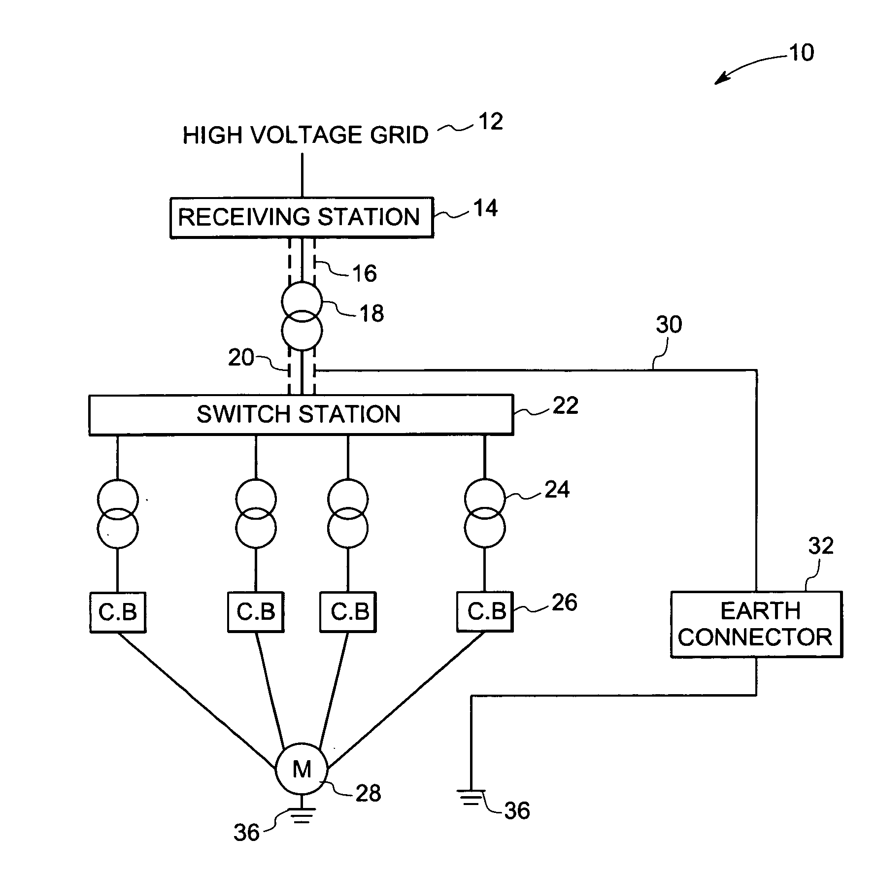
[0023]Ideally, three-phase alternating current (AC) power, as is used in most industrial environments, employs three conductors of electrical power each providing a pure sine wave of current and voltage, the sine waves having equal and constant amplitude and frequency, and each phase separated from the others by 120 degrees of phase angle.

[0024]With the increased use of solid-state power electronic devices, having non-linear load characteristics, such as motor controllers having switched triacs that connect and disconnect large loads rapidly, the three-phase power at a given facility may become distorted. Such distortion is characterized by the introduction of harmonics into the fundamental frequency of the AC power. Harmonics cause loss of energy in motors and may effect the efficiency and stability of power supplies in sensitive electronic equipment. Harmonics may also cause resonance resulting in unwanted voltage spikes. For these reasons limitations on harmonic levels in AC powe...


PUM


Abstract

A system for reducing resonance from harmonic distortion in a high voltage power system is presented. The system includes a voltage damper coupled to the high voltage power system between a cable sheath and an earth connection. The voltage damper is configured to clamp voltage peaks. The system also includes a frequency shifter coupled across the voltage damper and configured to displace a resonance frequency of the high voltage power system.

Description

BACKGROUND[0001]The invention relates generally to resonance in high voltage power systems and in particular, to a system and method for mitigating resonance from harmonic distortion.[0002]Converting alternate current (AC) power to direct current (DC) power and vice versa may include circuits such as rectifier networks with passive input and output filters that produce significant harmonic distortion of the AC current waveforms. Harmonic distortion typically causes undesirable power dissipation and creates unwanted electromagnetic interference that couples into other lines and equipment. Distorted AC current waveforms may also excite undesirable vibration in transformers, rotating machinery where electromagnetic couplings are implemented. In addition, input power factor is often adversely affected resulting in decreased operating efficiency.[0003]Other AC to DC power conversion approaches may involve active circuits utilizing various pulse width modulated (PWM) switching mode techni...

Claims


Application Information

Patent Timeline
IPC IPC(8): H02J1/02
CPCH02H9/005H02H7/228Y02E40/30H02J3/18H02J3/00125H02H7/26H02J3/01
Inventor SIHLER, CHRISTOF MARTINLARSEN, EINAR VAUGHNACHILLES, ALFREDO SEBASTIAN
Owner GENERAL ELECTRIC CO
Why Eureka
Try Eureka