Plasma processing apparatus

a processing apparatus and plasma technology, applied in the direction of electrical apparatus, electrical discharge tubes, basic electric elements, etc., can solve the problem of inability to control uniform temperature of electrode samples, in-plane temperature of electrode samples to be processed, etc., to inhibit excessive heat exchange

Inactive Publication Date: 2010-05-27
HITACHI HIGH-TECH CORP
View PDF9 Cites 234 Cited by
  • Summary
  • Abstract
  • Description
  • Claims
  • Application Information

AI Technical Summary

Benefits of technology

[0007]An object of the present invention is to provide a plasma processing apparatus and a plasma processing method that can keep a refrigerant in the state of a gas-liquid two-phase in a flow passage in an electrode in order to control the in-plane temperature of a sample to be processed uniformly by using a direct-expansion type cooling cycle.
[0008]Another object of the present invention is to provide a plasma processing apparatus and a plasma processing method that can control the in-plane temperature of a sample to be processed uniformly even in a direct-expansion type heating cycle.
[0010]The present invention makes it possible to uniformly control the in-plane temperature of an electrode, consequently the in-plane temperature of a wafer, by adjusting the enthalpy of a refrigerant supplied into an electrode flow passage and keeping the flow mode of the refrigerant in the electrode flow passage in the state of a gas-liquid two-phase flow. More specifically, the present invention makes it possible to inhibit excessive heat exchange between the refrigerant and water for heat exchange, keep the flow mode in the state of a gas-liquid two-phase flow in the electrode flow passage, and control the in-plane temperature of a sample to be processed uniformly by controlling the condensing capacity of the refrigerant immediately before the refrigerant flows into the electrode.
[0011]Further, the present invention makes it possible to provide a temperature adjusting unit for a sample table that can uniformly control the in-plane temperature of a wafer when high heat input etching is carried out by applying a high wafer bias electric power with a direct-expansion cycle.

Problems solved by technology

As a result, the temperature of an electrode, consequently the in-plane temperature of a sample to be processed on an electrode, cannot be controlled uniformly.

Method used


Image

  • Plasma processing apparatus
  • Plasma processing apparatus
  • Plasma processing apparatus

Examples


first embodiment

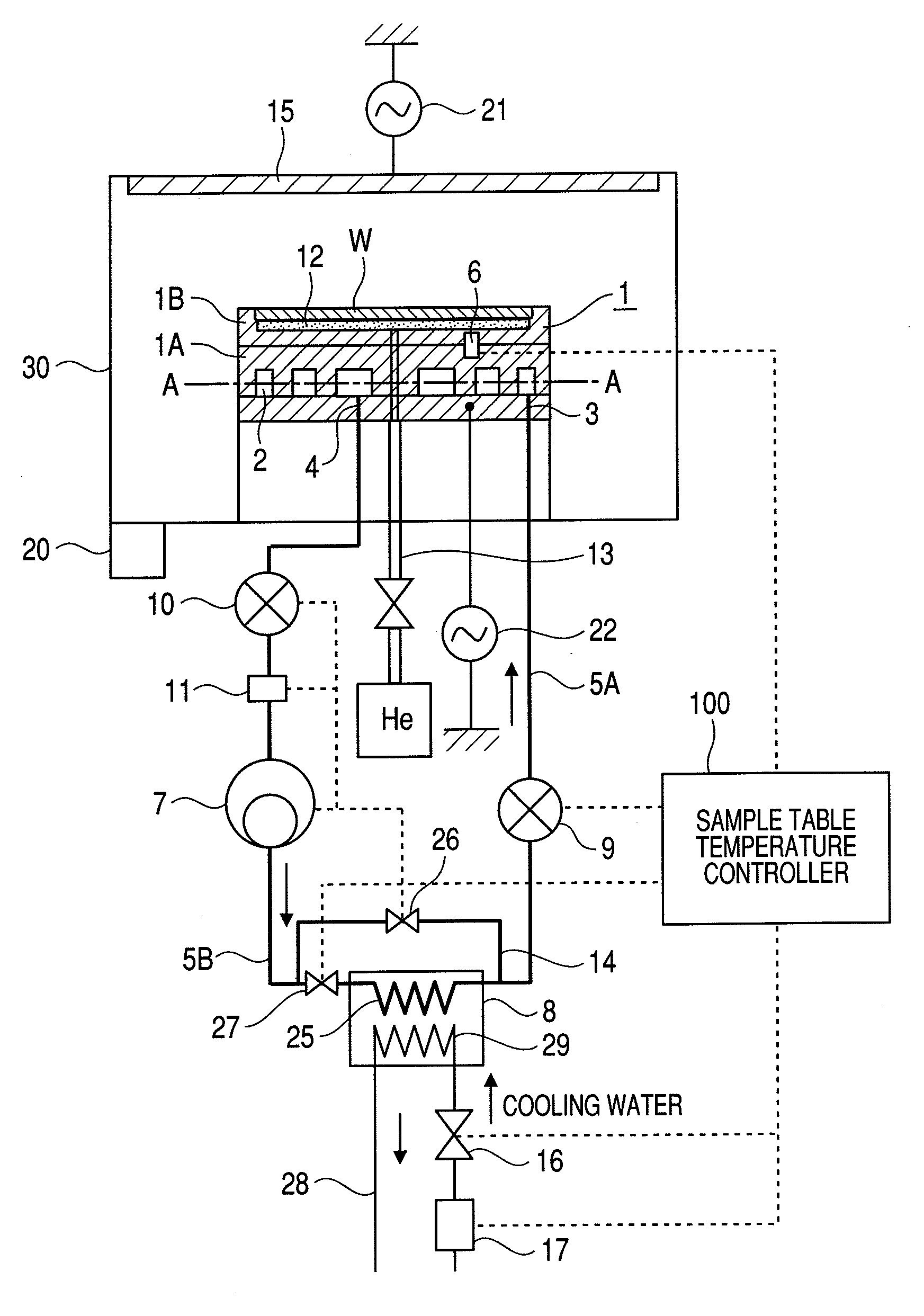
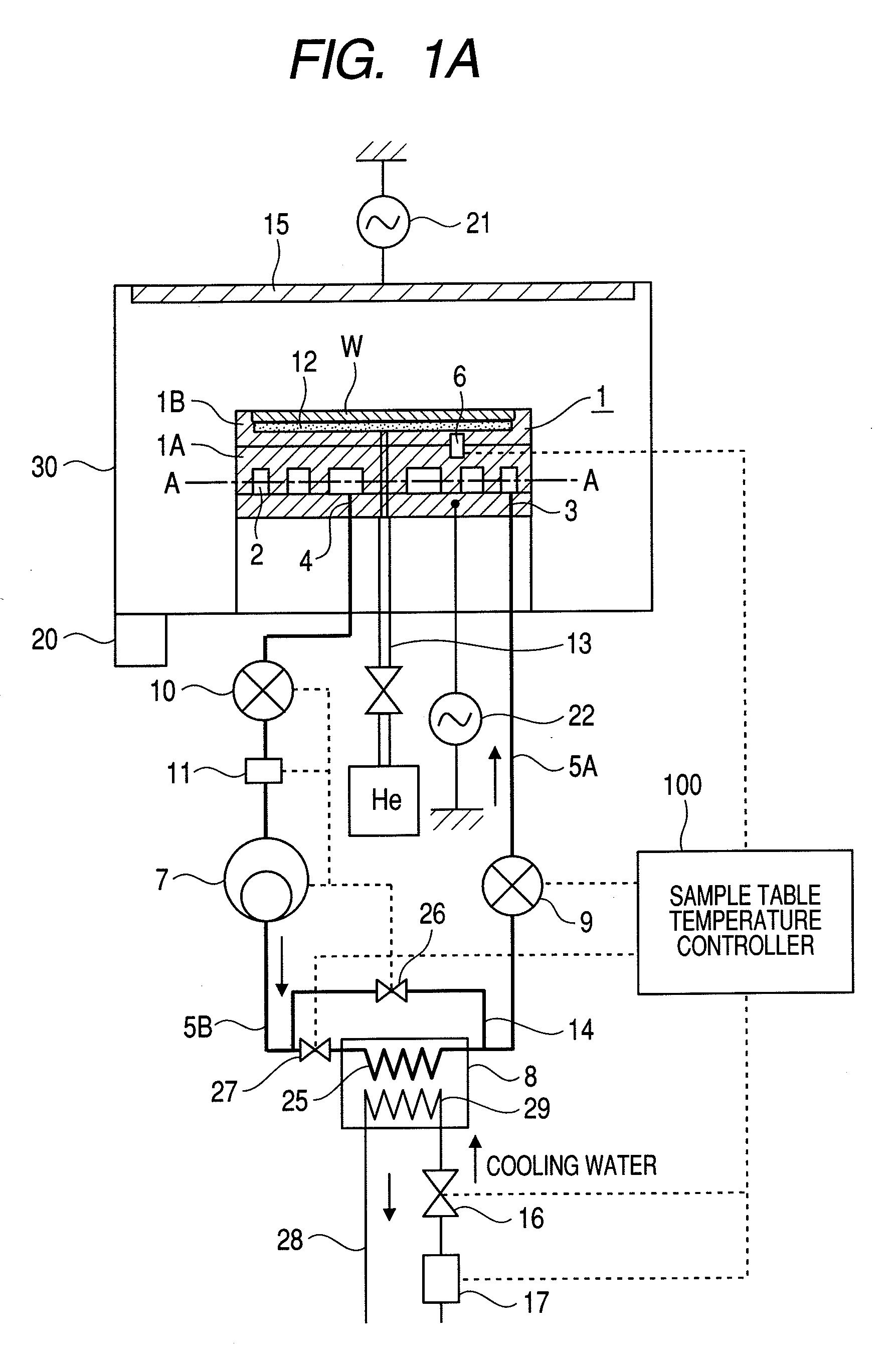
[0032]A first embodiment wherein the present invention is applied to a plasma processing apparatus as a cooling cycle to control the temperature of a sample table is explained in reference to FIGS. 1A to 5C.

[0033]FIG. 1A is a schematic diagram showing a general system configuration of a plasma processing apparatus according to the first embodiment of the present invention. The plasma processing apparatus has a processing chamber 30 installed in a vacuum chamber and a sample table 1 having an electrostatic adsorption electrode is placed in the processing chamber 30. Further, a vacuum evacuator 20, such as a vacuum pump, to evacuate and decompress the interior thereof is connected to the processing chamber 30. An electrode plate 15 is installed at the upper part of the processing chamber 30 and an antenna power source 21 to supply high-frequency power is connected to the electrode plate 15. Here, at the upper part of the processing chamber 30, a gas introducing means, such as a shower...

second embodiment

[0069]As the second embodiment according to the present invention, an embodiment wherein the present invention is applied to a plasma processing apparatus as a heat pump cycle to control temperature in both heating and cooling of a sample table is explained in reference to FIGS. 6 (FIGS. 6A and 6B) and 7.

[0070]When a heat pump cycle is used as a cooling cycle in the second embodiment, the basic configuration and function are the same as those of the cycle adopted in the first embodiment (refer to FIG. 1). An example of a switching mechanism of supply / discharge ports connected to a refrigerant flow passage 2 and controlled by a refrigerant supply / discharge direction switching control means 142 is shown in FIG. 6. The heat pump cycle includes a first heat exchanger (a refrigerant flow passage formed in a sample table 1) 2, a compressor 7, a second heat exchanger (a condenser) 8, a first expansion valve 9, a second expansion valve 10, and a refrigerant evaporating heater 11 (in a direc...

third embodiment

[0081]As the third embodiment of the present invention, an example of a direct-expansion type cycle equipped with void ratio measuring devices is explained in reference to FIGS. 8 to 10.

[0082]Firstly, the flow mode of the refrigerant used in the present embodiment is shown in FIG. 8. In FIG. 8, (a) shows the relationship between a degree of dryness and a heat transfer coefficient, (b) shows the relationship between a degree of dryness and a void ratio, and (c) shows the flow mode of the refrigerant in a cooling cycle. In general, a refrigerant of a hydrofluorocarbon type used in a cooling cycle shows the same trend as shown in FIG. 8. In the cooling cycle, the flow mode of the refrigerant changes from a liquid to a gas-liquid two-phase and then to a gas. On this occasion, bubbles, namely a void ratio, increases in the refrigerant in proportion to the change of the flow mode. The void ratio is 0 when the refrigerant is a liquid and is 1 when the refrigerant is thoroughly a gas. Conse...


PUM

PropertyMeasurementUnit
temperatureaaaaaaaaaa
temperature controllabilityaaaaaaaaaa

Abstract

In a plasma processing apparatus; a refrigerant flow passage being formed in the sample table and constituting an evaporator of a cooling cycle and the in-plane temperature of the sample to be processed is controlled uniformly by controlling the enthalpy of the refrigerant supplied to the refrigerant flow passage and thereby keeping the flow mode in the refrigerant flow passage, namely in the sample table, in the state of a gas-liquid two-phase. If by any chance dry out of the refrigerant occurs in the refrigerant flow passage because the heat input of plasma increases with time or by another reason, it is possible to increase speed of a compressor and inhibit the dry out from occurring in the refrigerant flow passage. Further, if the refrigerant supplied to the refrigerant flow passage is liquefied, it is kept in the gas-liquid two-phase state.

Description

CLAIM OF PRIORITY[0001]The present application claims priority from Japanese Patent Application 2008-302628 filed on Nov. 27, 2008, the content of which is hereby incorporated by reference into this application.FIELD OF THE INVENTION[0002]The present invention relates to a plasma processing apparatus and a plasma processing method for applying microprocessing to a sample such as a wafer in a semiconductor production process and in particular to a temperature controller and a temperature controlling method for controlling a temperature of an electrode to retain and fix a semiconductor wafer.BACKGROUND OF THE INVENTION[0003]As semiconductor devices become miniaturized, processing accuracy required for the etching of a sample increases. It is important to control the temperature of a wafer surface during etching in order to form a fine pattern on the wafer surface with a high degree of accuracy with a plasma processing apparatus. However, because of the demands for the increase of a wa...

Claims


Application Information

Patent Timeline
Patent Type & Authority Applications(United States)
IPC IPC(8): H01L21/3065
CPCH01J37/32522H01L21/67248H01L21/67109H01J2237/2001
Inventor TANDOU, TAKUMIYOKOGAWA, KENETSUIZAWA, MASARU
Owner HITACHI HIGH-TECH CORP
Why Eureka
Try Eureka