Cooling/heating panel

a technology of cooling/heating panels and heat exchange pipes, which is applied in the direction of lighting and heating apparatus, heating types, laminated elements, etc., can solve the problems of increasing the mass of the ceiling portion, the support member of the load on the ceiling material increases, so as to facilitate the mounting of the heat exchange pipe and achieve the effect of high thermal exchange efficiency, simple structure and high heat exchange efficiency

Active Publication Date: 2010-05-27
INTER CENT
View PDF6 Cites 9 Cited by
  • Summary
  • Abstract
  • Description
  • Claims
  • Application Information

AI Technical Summary

Benefits of technology

[0027]A cooling / heating panel of the present invention is adapted to easily mount a heat exchange pipe with a simple structure; thermal conduction between a metallic holding member and a resin heat exchange pipe is appropriate; and the metallic holding member is capable of reliably transmitting a temperature of a heat exchange fluid of the heat exchange pipe to a radiation panel. In this manner, the cooling / heating panel can be formed having high thermal exchange efficiency between the fluid flowing in the heat exchange pipe and the radiation panel and high energy efficiency.
[0028]In addition, in the case of comparison with a conventional metallic heat exchange pipe, a mass of the cooling / heating panel can be reduced, and considering the entire buildings, a reduction effect of the mass of the cooling / heating panel is significantly great. Further, the metallic heat exchange pipe is easily plastically deformable, and it is difficult to attach the pipe to the holding member so as to be repulsively in intimate contact therewith; and however, with a structure of the present invention, appropriate thermal conduction is obtained even in the resin heat exchange pipe.
[0029]In addition, a noninflammable sheet is provided at a portion other than a receptacle-mounted portion on the backside of the radiation panel, and even if a resin is used for the heat exchange pipe, noninflammable properties can be reliably obtained.
[0030]Further, the cooling / heating panel of the present invention is lightweight and has high thermal exchange efficiency, and is capable of restraining oxidization of connecting components.

Problems solved by technology

However, the above-described metallic heat exchange pipe as disclosed in Patent Document 1 of the prior art is large in mass; a load upon a ceiling material increases; a support member of the ceiling material increases and becomes heavy; and as a whole, the mass of a ceiling portion increases.
As a result, a structure such as earthquake proof of buildings has been thereby affected.
Moreover, a metallic heat exchange pipe is hardly processed in a meandering shape, and is easily plastically deformed.
For example, if a metallic heat exchange pipe is attached to a pipe holding portion of a ceiling material, the pipe must be attached in a deformation quantity within an elastic limit in order for the pipe to be elastically deformed and repulsively intimately contacted, thus making it difficult to provide dimensional setting such that the pipe is hardly detached and can be elastically held.
Therefore, elastic holding is realistically difficult, and the pipe cannot be mounted while a full surface is in intimate contact with the holding portion all over the full length of the heat exchange pipe.
Further, between the heat exchange pipe at which the full surface is not in intimate contact therewith and its holding portion, thermal conduction is not good due to the presence of a spatial layer, resulting in a failure to exploit the virtue of thermal conduction of a metal.
In addition, like the abovementioned Patent Document 2, in the case of a structure in which a heat exchange pipe is held between metal plates, with the heat exchange pipe being precisely positioned on a radiation panel, a metallic soaking plate must be fixed so as to cover the radiation panel at a predetermined position, making assembling or construction difficult and increasing the number of man-hours.
Therefore, a cooling / heating panel and cooling / heating equipment employing the panel has been prone to become high in cost.
Therefore, unlike a metal, a heat cannot be reliably efficiently transmitted, and thermal efficiency of the cooling / heating equipment has become lowered.

Method used


Image

  • Cooling/heating panel
  • Cooling/heating panel
  • Cooling/heating panel

Examples


first embodiment

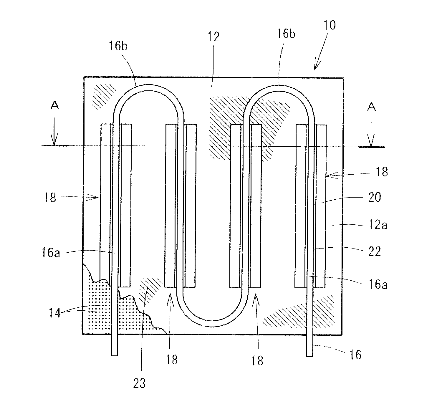
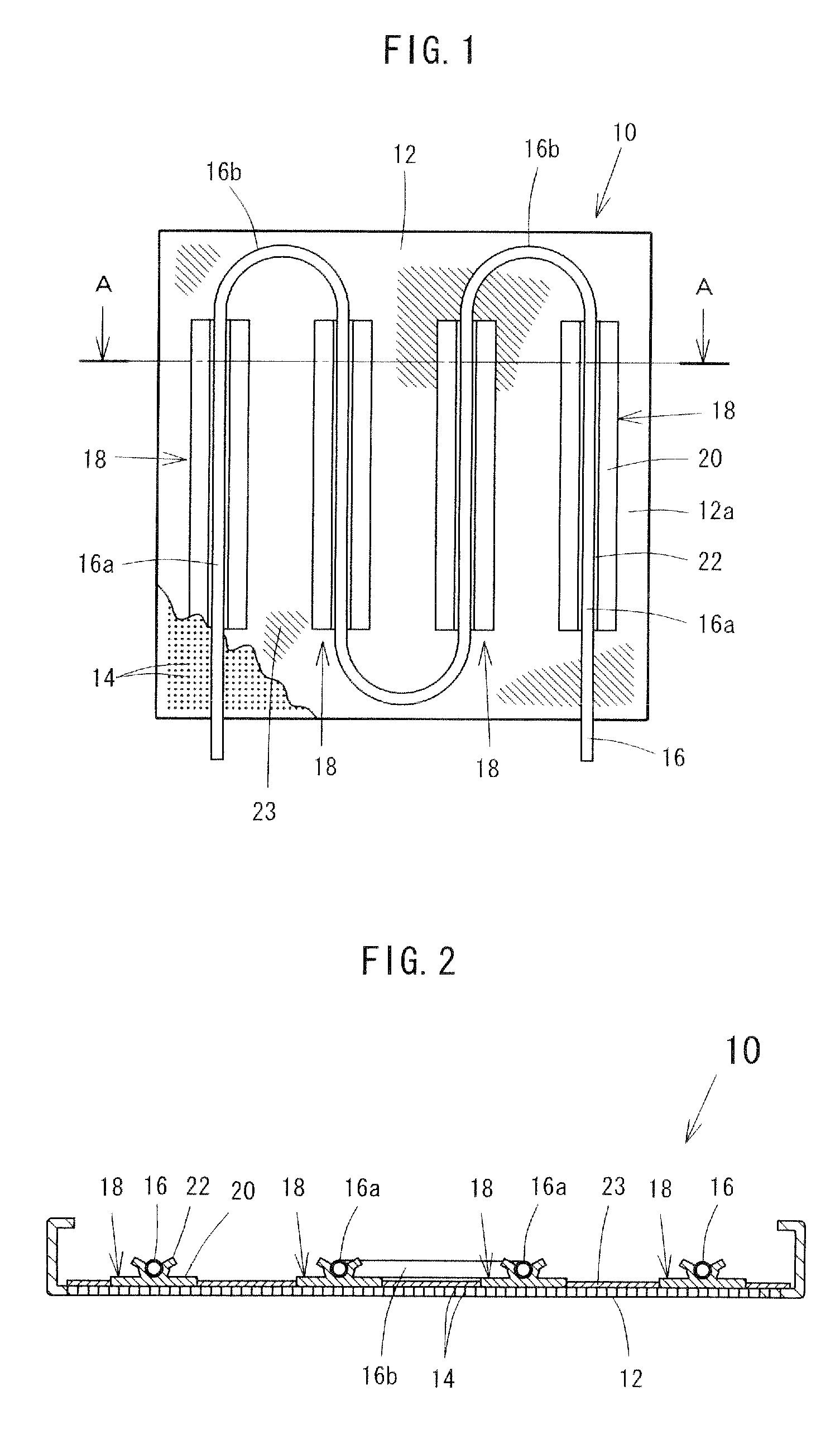
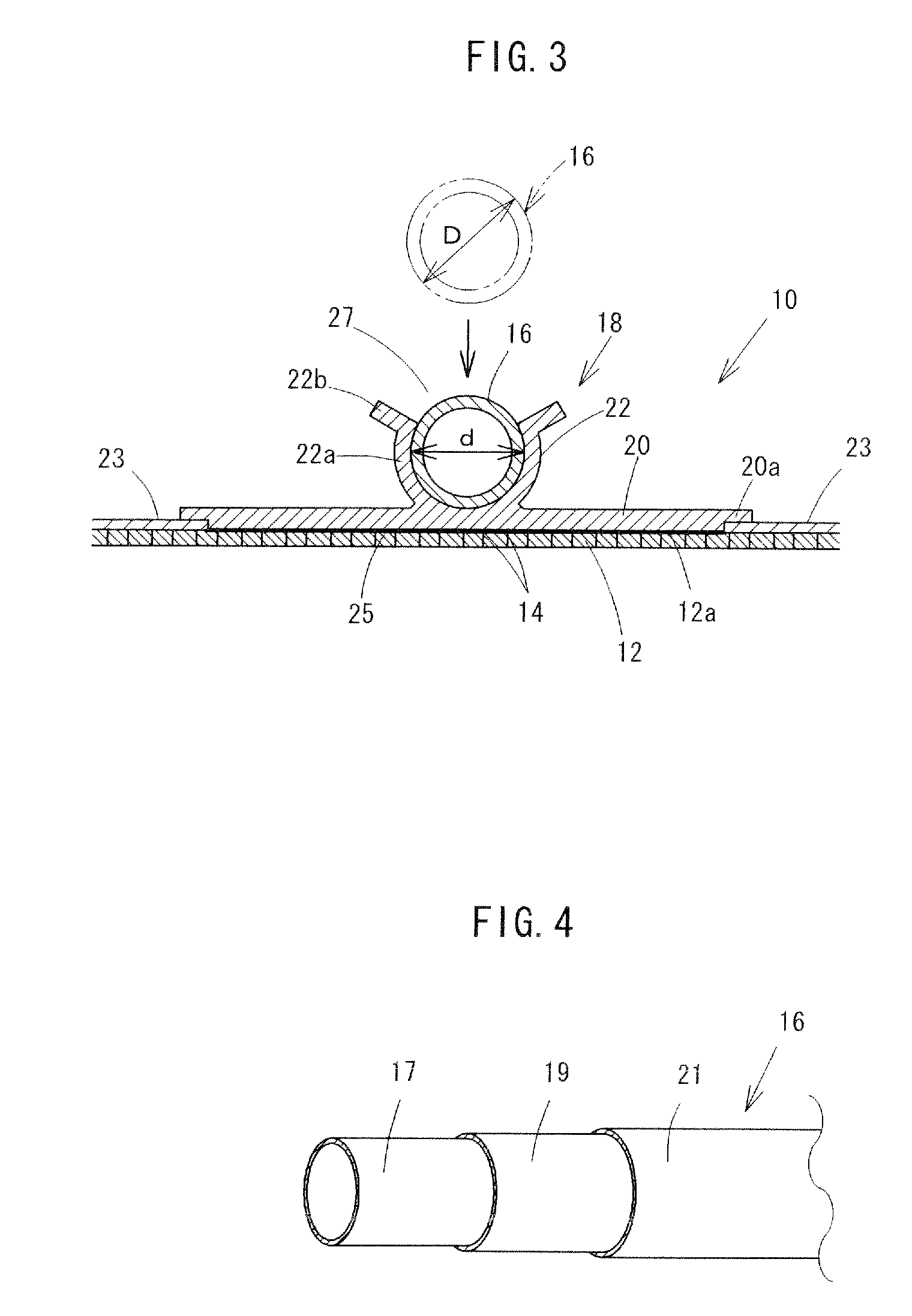
[0055]Hereinafter, embodiments of the present invention will be described referring to the drawings. FIGS. 1 to 5 show the present invention, and a cooling / heating panel of the embodiment is a ceiling-mounted cooling / heating panel 10, and is provided with a planar radiation panel 12. The radiation panel 12 is molded with: a metal plate formed of aluminum or iron; a plaster board; or concrete, and a plurality of acoustic absorption holes 14 are perforated and formed. On a backside 12a of the radiation panel 12, a heat exchange pipe 16 is provided to be held by means of a holding member 18 as described later. In the heat exchange pipe 16, straight portions 16a crossing a unidirectional width of the radiation panel 12 and curved portions 16b returning while they are curved before reaching an end part of the radiation panel 12 are alternately formed, and consecutively meander.

[0056]On the backside 12a of the radiation panel 12, as shown in FIGS. 1 to 3, the holding members 18 for holdin...

second embodiment

[0070]Next, the present invention will be described referring to FIGS. 7 and 8. Hereinafter, like constituent elements in the above-described embodiment are designated by like reference numerals and a duplicate description is omitted. In a ceiling-mounted cooling / heating panel 42 of the embodiment as well, holding members 44 for holding the straight portions 16a of the heat exchange pipe 16 are mounted on the backside 12a of the radiation panel 12. The holding members 44 are formed of a metal such as an aluminum-extruded material; are elongated members mounted along the straight portions 16a of the heat exchange pipe 16; and are uniform in the cross-sectional shape of a longitudinal direction. Soaking plates 46, which are plate bodies superimposed on the backside 12a of the radiation panel 12, are provided at the holding members 44, and holding portions 22 are provided at the cores of the soaking plates 46. The holding members 44 are mounted from end to end of the radiation panel 12...

third embodiment

[0074]Next, the present invention will be described referring to FIGS. 9 to 12. Hereinafter, like constituent elements of the above-described embodiments are designated by like reference numerals and a duplicate description is omitted. In a ceiling-mounted cooling / heating panel 50 of the embodiment as well, the holding members 18 for holding the straight portions 16a of the heat exchange pipe 16 are mounted on the backside 12a of the radiation panel 12.

[0075]The heat exchange pipe 16 of the embodiment is mounted on the holding portion 22 while the pipe is curved at every interval in the same direction relative to the holding member 18 fixed to the radiation panel 12.

[0076]The ceiling-mounted cool panel 50 of the embodiment also has a similar advantageous effect by the use method similar to that of the above-described embodiments, and a curving direction of the heat exchange pipe 16 is uniform, so that the heat exchange pipe 16 is curved in the direction of the winding habit of the h...


PUM


Abstract

A cooling / heating panel has a planar radiation panel (12), a metallic holding member (18) arranged partially on a backside of the radiation panel (12), and a resin heat exchange pipe (16) held by the holding member (18). The holding member (18) has: a flat soaking plate (20) which is superimposed on the radiation panel (12); and a holding portion (22) which is erected on the soaking plate (20) and latches the heat exchange pipe (16). The heat exchange pipe (16) has an outside diameter larger than an inside diameter of the holding portion (22) before the heat exchange pipe (16) is attached to the holding portion (22) and in a state in which the heat exchange pipe (16) is attached to the holding portion (22), the holding portion (22) holds a side face of the heat exchange pipe (16) repulsively from both sides.

Description

TECHNICAL FIELD[0001]The present invention relates to a cooling / heating panel which performs interior cooling or heating by means of radiation heat obtained by heat exchange via a fluid.BACKGROUND ART[0002]Conventionally, a radiation-type cooling / heating panel constructed on ceiling has been known. Such a cooling / heating panel has a radiation panel made of a metal or a plaster board; a metallic or resin heat exchange pipe is disposed at a backside of the radiation panel; and this cooling / heating panel is installed on a ceiling. A fluid of a predetermined temperature is flowed in the heat exchange pipe installed on the ceiling, and interior cooling / heating is performed.[0003]As a ceiling cooling / heating panel having a metallic pipe, like a ceiling element disclosed in Patent Document 1, there is the one in which a metallic heat exchange pipe such as copper is mounted on a backside of a ceiling cooling / heating panel. The metallic heat exchange pipe per se has appropriate thermal condu...

Claims


Application Information

Patent Timeline
Patent Type & Authority Applications(United States)
IPC IPC(8): F28F3/00
CPCF24D3/146F24F5/0092F24F5/0089F24D3/165Y02B30/00
Inventor MIYAMURA, MASASHIYAMAGISHI, HIROSHIKANAI, KATSUMASA
Owner INTER CENT
Why Eureka
Try Eureka