Method and an Apparatus for the Supply of a Gas

a gas supply and gas technology, applied in the field of gas supply methods and apparatuses, can solve the problems of extremely sensitive to gas flow variations, rarely up to 30 minutes, and relatively long heating time, and achieve the effects of increasing the thermal transfer surface area of the shell, increasing the efficiency of the heating process, and increasing the application effect of hot gas

Inactive Publication Date: 2010-05-27
TETRA LAVAL HLDG & FINANCE SA
View PDF3 Cites 0 Cited by
  • Summary
  • Abstract
  • Description
  • Claims
  • Application Information

AI Technical Summary

Benefits of technology

[0012]According to still another further developed version of the present invention, the shell is formed in a manner adapted in respect of the pertinent practical application. This may be put into effect in that the shell which constitutes the heating unit and which at the inlet side consists of undeformed electrically conductive hoses / tubes is, in the area of the site of application for the generated hot gas through adaptation formation of such a hose element, given a form which closely fits the pertinent application. For example, this formation may be put into effect by vacuum formation. The emission of the hot gas suitably takes place via holes provided in the hose shell which may possibly be specially designed. By such a special design, gas at an extremely accurately controlled temperature can be supplied to the application site which would otherwise be a practical impossibility to achieve, and thereby also the effect of the application of the hot gas will be increased.
[0013]According to still another further developed version of the present invention, the inside of the shell is formed with flange-like projections. Hereby, the thermal transfer surface area of the shell is increased, which increases the efficiency of the heating process.
[0014]According to yet another further developed version of the present invention, a penetrated of foraminated hose shell is supplied with gas or gas mixture from both of its ends. This entails above all that a larger gas volume can be supplied per unit of time, with the result that the heating stage can no longer be seen as a bottleneck section.
[0015]According to still another further developed version of the present invention, the shell is exteriorly thermally insulated. This quite naturally results in a reduction of the unintentional loss of heat volume into the ambient atmosphere, which is both economically and environmentally positive.

Problems solved by technology

Typical for such filaments enclosed in ceramic material or glass is that, by being enclosed in the described manner and as a result of their relatively large thermal mass, they have a relatively long heating time, not seldom up towards 30 minutes.
Moreover, they are extremely sensitive to variations in the gas flow.
Gas flow variations however lead, in the worst case, to the filament or its enclosure being overheated and that the filament or the enclosure are quite simply broken down, with unnecessary and costly operational downtime as a result.
In connection with operational downtime of this type, it may moreover be difficult to maintain control over the spread of particles from destroyed elements or filaments.
For the above-outlined reasons, this is not possible to achieve using a traditional solution.
Nor can the generation of hot gas be guaranteed at an acceptably reliable temperature level until perhaps 30 minutes after initiation.
What is more, prior art solutions represent the not inconsiderable problem that the heated gas constitutes a major source of severe energy losses of perhaps up towards 300 W / dm2 tube surface, in that it is transported in uninsulated tubes to its application site.
For natural reasons, this is not desirable, either from the cost viewpoint or against the background of local heating occurring in such cases of areas in a machine where this is not desirable.
At the same time, such an undesirable local heating most often entails an undesirable heating of the ambient surroundings of the machine.

Method used


Image

  • Method and an Apparatus for the Supply of a Gas
  • Method and an Apparatus for the Supply of a Gas
  • Method and an Apparatus for the Supply of a Gas

Examples


Embodiment Construction

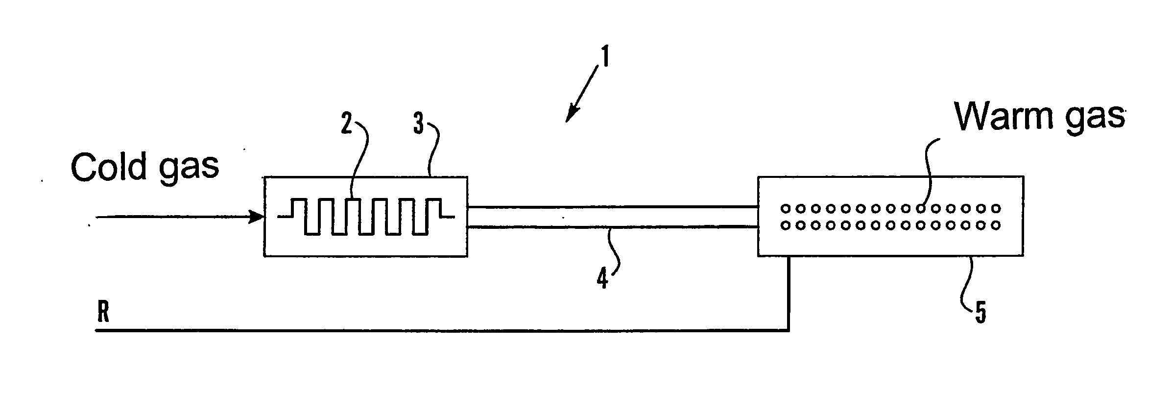
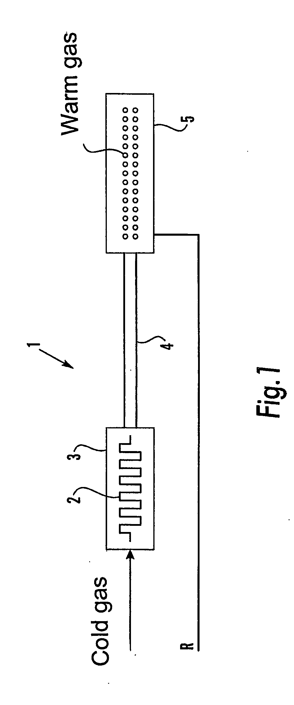
[0022]FIG. 1 shows an apparatus 1 which reflects a hitherto applied mode of approach which is employed in order to make possible a powerful temperature elevation of a gas or gas mixture. Cold gas or gas at normal temperature is fed in at the left-hand end of the apparatus 1 shown in the figure to a heating element 2 which comprises one or more filaments surrounded by one or more ceramic elements 3. The ceramics elements 3 are, because they are intended to store and emit a relatively large quantity of energy and because they are thermally insulated, relatively bulky and can, int. al. for this reason, not be placed in association with the site of application for the hot gas. Consequently, the heated gas is led into conduits 4 in order to be conveyed out to these positions where the nozzles 5 are disposed. In or at the nozzles 5, temperature sensors (not shown) are connected in whose signals are fed back to a regulator unit R.

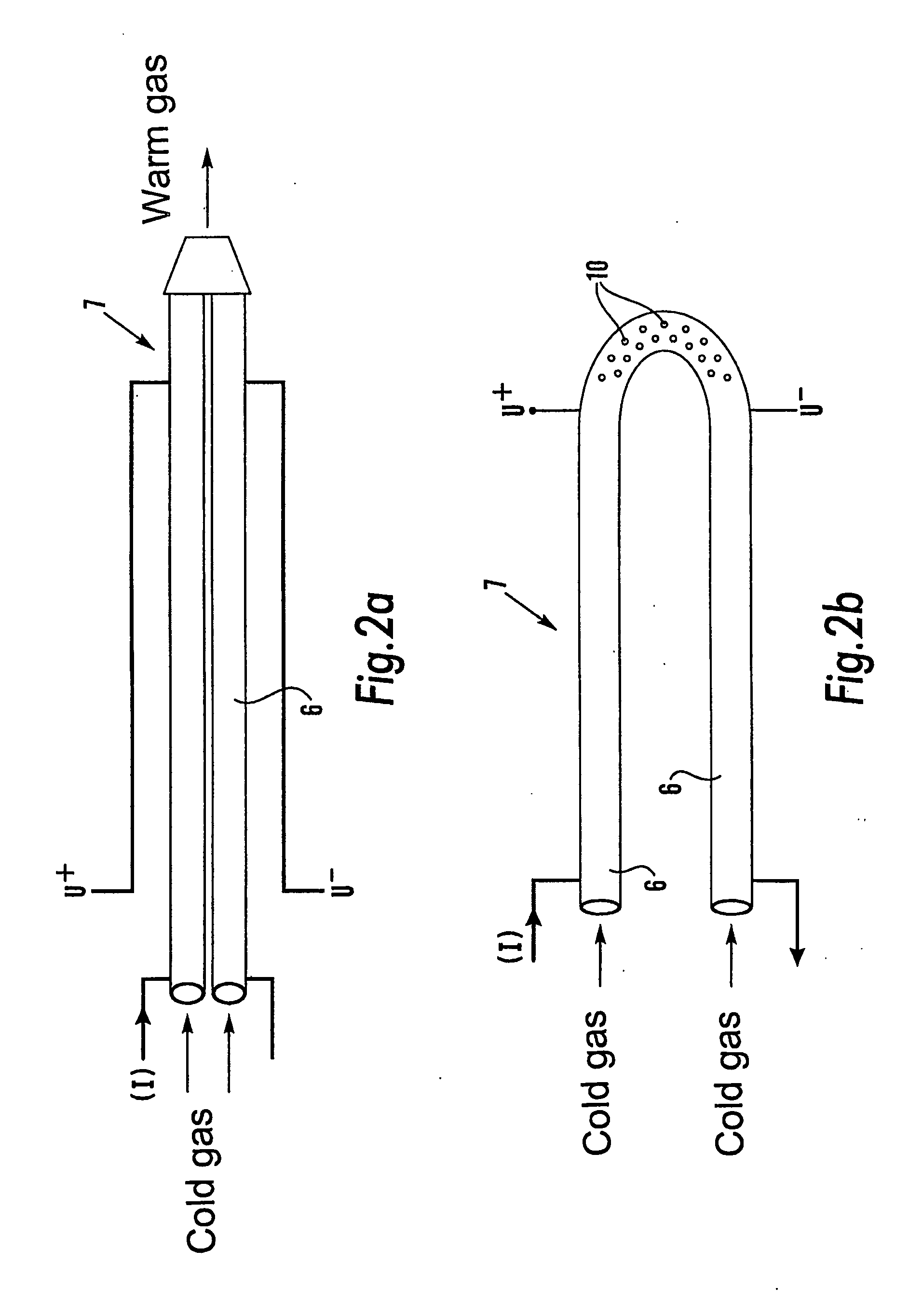
[0023]FIG. 2a shows an apparatus 7 for realising the mode of...


PUM

PropertyMeasurementUnit
lengthaaaaaaaaaa
lengthaaaaaaaaaa
temperatureaaaaaaaaaa

Abstract

The invention relates to a method and an apparatus for the supply of a gas or a gas mixture at a predetermined temperature to a processing station in a filling machine in which gas or gas mixture pressurised to above atmospheric is passed through an electrically heated heating unit (2, 3; 6, 7). This includes a sensor sensing the temperature of the gas whose output signal is fed back to a gas temperature regulator unit (not shown) which in its turn is coupled to the heating unit with a view to regulating the temperature of the gas flowing out from the heating unit (2, 3; 6, 7). The heating unit (7) is formed to an electrically conductive shell or a cavity (6) through which the gas or gas mixture is passed positively and regulated. In such instance, the shell (7) is coupled to a voltage regulated via a regulator unit in an electric current circuit, as a result of the current which is driven by the circuit and as a consequence of the resistance of the material, the shell being heated up and thereby the gas and the gas mixture, whereafter the temperature in the shell is registered and fed back to the regulator unit which regulates the voltage against a gas temperature which corresponds to that which is desired to flow out from the shell or the cavity (6).

Description

TECHNICAL FIELD[0001]The present invention relates to a method and an apparatus for the supply of a gas or a gas mixture at a predetermined optional temperature and optional flow in any arbitrary application in a filling machine. In the description below, use will be made of the term gas generically also as a designation for any optional gas mixture. In greater detail, the present invention relates to a method and an apparatus in connection with the supply of a gas at a predetermined temperature to a processing station in a filling machine. In the machine, gas pressurised to above atmospheric pressure is passed through an electrically heated heating unit which includes a sensor which senses the temperature of the gas. The output signal from this sensor is fed back to a gas temperature regulator unit which in turn is connected to the heating unit with a view to regulating the temperature of the gas flowing out from the heating unit.[0002]Traditionally, apparatuses of the above-outlin...

Claims


Application Information

Patent Timeline
Patent Type & Authority Applications(United States)
IPC IPC(8): H05B1/02F24H9/20F24H1/10B67D7/80B65B57/00F24H3/04F24H15/25
CPCF24H3/0405B65B57/00F24H9/2071H05B3/0014F24H15/25
Inventor INGVERT, CLAES
Owner TETRA LAVAL HLDG & FINANCE SA
Why Eureka
Try Eureka