Telemetry system for ship propulsion systems

a technology of propulsion system and telemetry system, which is applied in the direction of transmission system, propulsive element, electrical apparatus, etc., can solve the problems of high repair and downtime costs, affecting the construction of sensor system for controllable pitch propellers and steerable thrusters in marine machinery, and affecting the location and construction of the sensor system

Inactive Publication Date: 2010-05-27
WARTSILA PROPULSION NETHERLANDS +1
View PDF7 Cites 25 Cited by
  • Summary
  • Abstract
  • Description
  • Claims
  • Application Information

AI Technical Summary

Benefits of technology

[0010]Advantageously, in a first embodiment this arrangement allows measurement of signals at specific points within the machinery without any restrictions imposed by the mechanical construction of the machinery.
[0013]Control and actuation of the propeller blades of a controllable pitch propeller, or individual control and actuation of each propeller blade of an adjustable pitch propeller can be done locally in the propeller hub while a tremendous complicated construction for providing control and actuation signals to the propeller can be avoided.

Problems solved by technology

If in such cases a failure occurs, costs for repair and downtime may be high.
Sensor systems for controllable pitch propellers and steerable thrusters in marine machinery are hampered in their construction by limiting conditions originating from the mechanical construction of these devices.
Similar difficulties in relation to location and construction of the sensor system arise when measurements on rotating parts of a diesel engine, such as its crankshaft, are required.
However, this technique may be adversely affected by mixing and / or damping of signals that propagate towards the at least one sensor.
Besides condition monitoring for steerable thrusters, there is a similar difficulty for actuation and control of pitch propellers (CPP).
This has large draw-backs with respect to the accuracy of the pitch setting.

Method used


Image

  • Telemetry system for ship propulsion systems
  • Telemetry system for ship propulsion systems
  • Telemetry system for ship propulsion systems

Examples


first embodiment

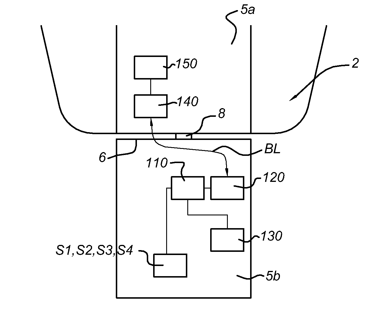
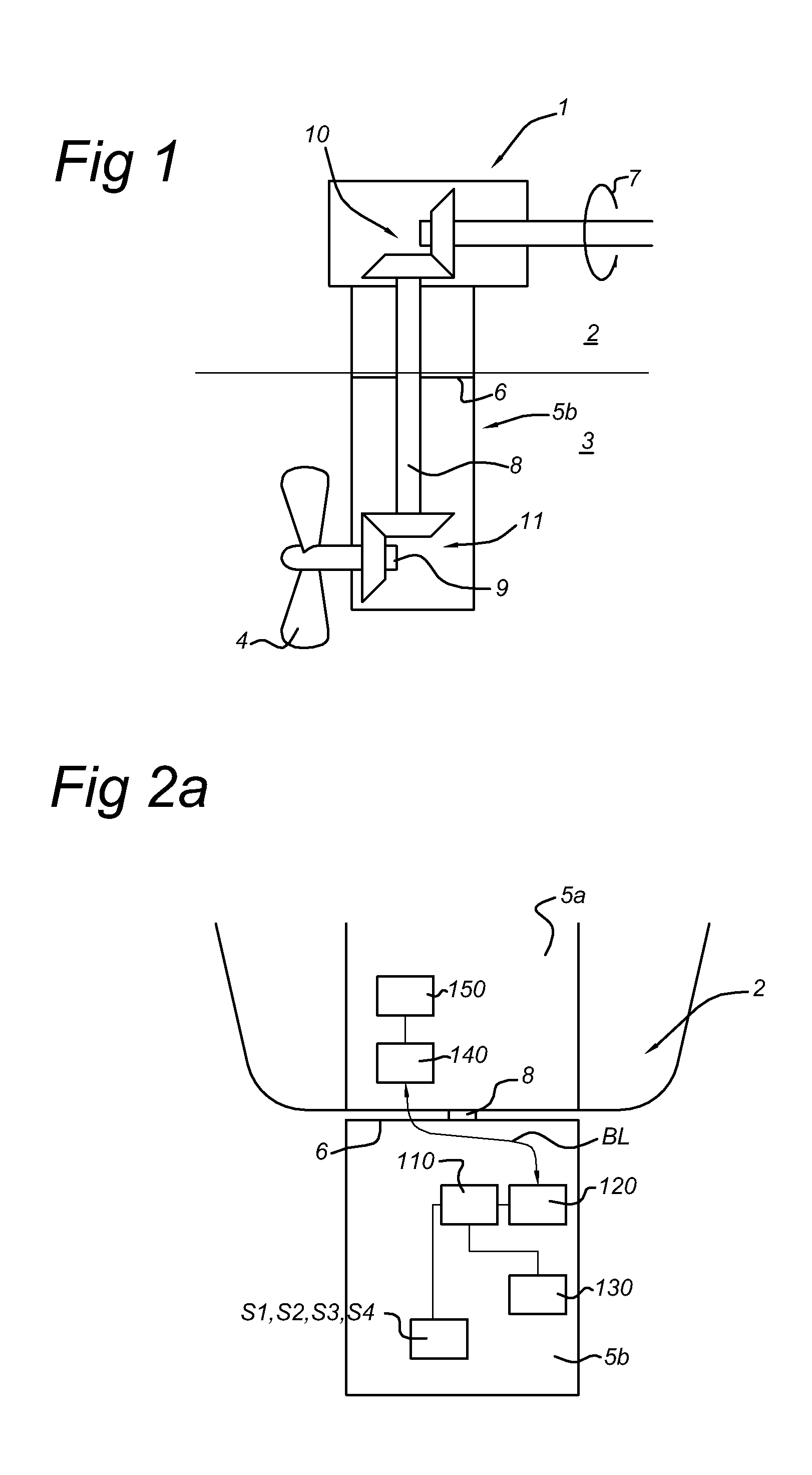
[0026]FIG. 1 shows a cross-sectional view of a thruster which comprises the arrangement according to the present invention.

[0027]A marine vessel such as a ship or an oil drilling rig can be provided with a plurality of controllable pitch propellers and steerable thrusters which are capable of maintaining the vessel's position or course during operation. Typically, a thruster is steerable and can be controlled to provide thrust in a given direction relative to the hull of the vessel. The thrust direction and thrust magnitude can be controlled. The thrust magnitude is achieved by installing a fixed pitch propeller driven by a motor or engine, which can vary the rotational speed, or by a controllable pitch propeller. To allow maneuverability of the vessel to an extent as large as possible, the thruster typically is arranged to be rotatable over 360° or more (relative to the longitudinal axis of the vessel).

[0028]It is noted that present invention also generally relates to machinery wit...

second embodiment

[0093]In the second embodiment the ferromagnetic yoke Y comprises two magnets M, which are coupled by a ferromagnetic coupling F between an S pole of one magnet M and an N pole of the other magnet M. The ferromagnetic coupling F is enclosed by the electromagnetic coil C.

[0094]When a magnetic field generated by the two magnets is sufficiently strong, there is no need for the placements of magnets on the shaft. In that case, an oscillation of the magnetic field within the electromagnetic coil C can be obtained by placement of metal teeth T on the axis 8, 9 that move, during rotation of the axis, along the ferromagnetic yoke Y.

[0095]Preferably, the metal teeth T on the axis 8, 9 are made of the same material as the axis, e.g. steel. Alternatively, other metals may be used as well.

[0096]It is noted that the power generator 130 of the second embodiment may have a lower efficiency than the power generator of the first embodiment, but depending on the required output power the second embod...

third embodiment

[0116]FIG. 8 shows a cross-sectional view of an adjustable pitch propeller arrangement APP which comprises the telemetry system according to the present invention.

[0117]In FIG. 8 entities with the same reference number as shown in the preceding figures refer to the corresponding entities in the preceding figures.

[0118]An adjustable pitch propeller APP is configured in that a pitch of each propeller blade is adjustable individually. The adjustable blades of the propeller (schematically indicated by lines 50, 51, 52, 53) are arranged at an end of a drive axis 18, which at the other end is coupled to an engine (not shown).

[0119]A cross-section of the adjustable pitch propeller APP along line IX-IX is schematically shown in FIG. 9.

[0120]The setting of the pitch of the adjustable blades 50, 51, 52, 53 is done by an hydraulic system, which comprises an hydraulic pump 550 and a controller 500.

[0121]The hydraulic pump 550 supplies an flow of a fluid to a power generator 132 (described above...


PUM


Abstract

Telemetry system for a ship propulsion system with a stationary part and a movable part that is movable relative to the stationary part. The telemetry system includes a processor, a data acquisition unit, at least one sensor, and a local power source. The processor, the at least one sensor and the power source are arranged in the movable part. The at least one sensor can measure an operational state of the movable part. The processor is connected to the at least one sensor for receiving signals from the at least one sensor and can transmit the received signals to the data acquisition unit. The local power source is arranged for providing power to at least one of the processor and at least one sensor, and the transmission of the received signals is arranged by a wireless communication link between the processor and the data acquisition unit.

Description

FIELD OF THE INVENTION[0001]The present invention relates to a telemetry system for a ship propulsion system. Also, the present invention relates to a method for a telemetry system for a ship propulsion system.BACKGROUND OF THE INVENTION[0002]Mechanical failures in large marine machinery such as controllable pitch propellers, steerable thrusters and (diesel) engines are of main concern for the utilization of this machinery. Typically, marine machinery is intended to work under specific conditions, for example at remote locations, under sometimes extreme environmental conditions and for extended periods of time. If in such cases a failure occurs, costs for repair and downtime may be high.[0003]For this reason, the machinery is monitored by a sensor system to observe the condition of the machinery. Typically, the condition is derived from machine parameters such as oil pressure and temperature, process temperature, vibration data, (engine) power, fuel consumption, cooling characterist...

Claims


Application Information

Patent Timeline
Patent Type & Authority Applications(United States)
IPC IPC(8): G01M17/00H04Q9/00G06F19/00G05D1/00
CPCG08C2201/51H04Q2209/40H04Q9/00B63H5/125B63H2005/1256
Inventor WESSELINK, ALBERT FREDERIKHEERKENS, BOBCLERMONTS, FRANCISCUS MARIA HENRICUS
Owner WARTSILA PROPULSION NETHERLANDS
Why Eureka
Try Eureka