Imaging optical system, image reading apparatus and image reading apparatus using the imaging optical system

a technology of imaging optical system and image reading apparatus, which is applied in the direction of optics, instruments, electrical devices, etc., can solve the problems of difficult to find out the optimum conditions for all factors, and the ghost may not be prevented, so as to achieve the effect of reducing the size of the imaging optical system and simplifying the manufacturing process

Inactive Publication Date: 2010-05-27
NIPPON SHEET GLASS CO LTD
View PDF1 Cites 14 Cited by
  • Summary
  • Abstract
  • Description
  • Claims
  • Application Information

AI Technical Summary

Benefits of technology

[0013]In case of an imaging optical system comprising a slit, a location adjustment between a slit and a sensor array is required in a manufacturing process. If all of ghost are prevented without using a slit, the manufacturing process may be further simplified and the size of an imaging optical system may be smaller.
[0014]Herein, the meaning of “ghost is not generate

Problems solved by technology

However, if a slit, a lens array plate, a sensor array, and the like are not subjected to an accurate location adjustment, a problem such that ghost may not be prevented occurs.
Therefore, it is very difficult to find out the optimum conditions for all of the factors, and then the design values by which ghost is least generated are conventionally determined by roughly varying one or two parameters of the factors such as the width of a slit, the location of a slit, and the like with the parameters of certain factors such as the ap

Method used


Image

  • Imaging optical system, image reading apparatus and image reading apparatus using the imaging optical system
  • Imaging optical system, image reading apparatus and image reading apparatus using the imaging optical system
  • Imaging optical system, image reading apparatus and image reading apparatus using the imaging optical system

Examples


Embodiment Construction

[0070](Explanation for an Imaging Optical System, an Image Reading Apparatus, and an Image Writing Apparatus)

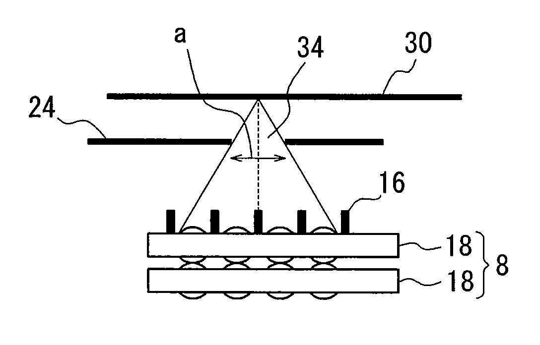
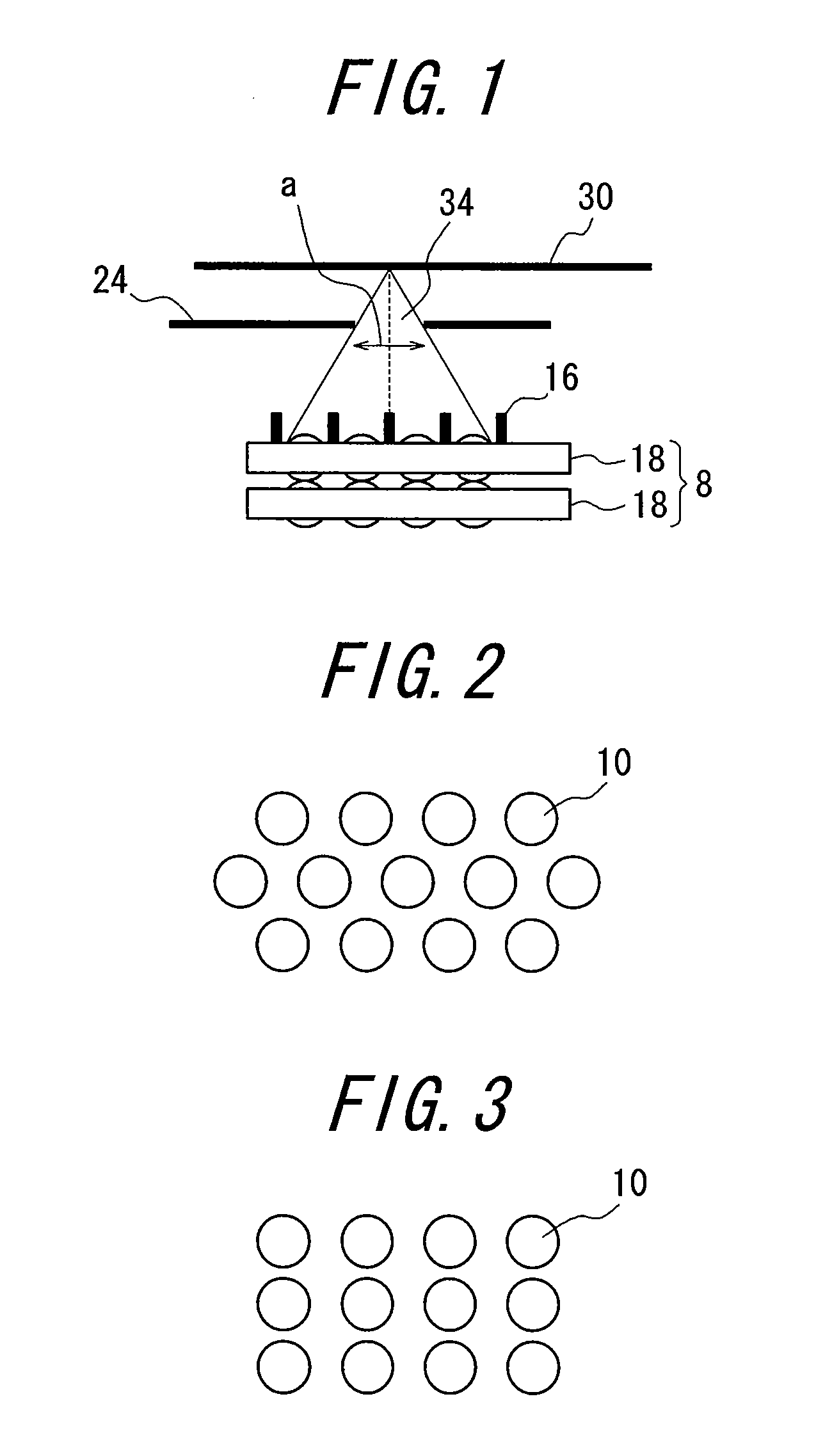
[0071]An imaging optical system used for an image reading apparatus such as an image scanner, a copy machine, or the like comprises an object plane, a lens array for transmitting the light from the object plane, and a sensor array (a photoelectric conversion element) arranged at an imaging position of the light transmitted through the lens array.

[0072]An imaging optical system used for an image writing apparatus such as a laser printer comprises an object plane, a lens array for transmitting the light from the object plane, and an image writing plane (a photosensitive drum) arranged at an imaging position of the light transmitted through the lens array.

[0073]An image reading apparatus is composed of an imaging optical system, an original plate such as an original glass plate, and an irradiating apparatus which are integrally accommodated in a housing. An image writing apparat...


PUM


Abstract

An imaging optical system a high quality image may be implemented by determining the optimum design conditions for suppressing the generation of ghost while holding uniform and sufficient light using a simulation method. In the imaging optical system having a slit, the requirements for removing the stray light are the inclination of a lens arrangement direction, the slit width, the lens pitch, the view angle, and the height of the light-shielding wall. The slit location, the lens thickness, and the lens row width do not affect the stray light removal, but affect the brightness. In the imaging optical system having no slit, the essential requirements for removing the stray light are the height of the light-shielding wall and the lens pitch. The lens thickness and the lens row width do not affect the stray light removal, but affect the brightness.

Description

TECHNICAL FIELD[0001]The present invention relates to an imaging optical system to transfer an image to a linear imaging area using a resin erected lens array, and an image reading apparatus and an image writing apparatus using the imaging optical system.BACKGROUND ART[0002]An imaging optical system comprises an optical source, a lens, a sensor array (CCD etc.), and a case (housing) for accommodating these components as described in Japanese Patent Publication No. 167778 / 1993.[0003]An imaging optical system used in an image reading apparatus has a structure for irradiating an original by the light outputted from an light source, collecting the light reflected on the original by a lens, and acquiring the collected light by a sensor array. When the light reflected from the original is inputted into the lens to be acquired by the sensor array, flare and ghost may be generated depending on the structure of an optical system, resulting in the decrease of an image quality.[0004]In order t...

Claims


Application Information

Patent Timeline
IPC IPC(8): G02B27/12
CPCG02B3/0062H04N1/0311G02B27/0018G02B3/0068G02B3/00H04N1/028H04N1/036
Inventor NAGATA, HIDESHIHAMANAKA, KENJIRONEMOTO, HIROYUKI
Owner NIPPON SHEET GLASS CO LTD
Why Eureka
Try Eureka