Check patentability & draft patents in minutes with Patsnap Eureka AI!

Vehicle hybrid driving apparatus

a hybrid driving and vehicle technology, applied in the direction of engine-driven generator propulsion, transportation and packaging, etc., to achieve the effect of improving fuel economy and reducing the size of the apparatus

Inactive Publication Date: 2010-05-27
TOYOTA JIDOSHA KK
View PDF1 Cites 21 Cited by
  • Summary
  • Abstract
  • Description
  • Claims
  • Application Information

AI Technical Summary

Benefits of technology

[0009]The invention provides a vehicle hybrid driving apparatus that has an engine and an electric motor as drive power sources, and that is able to achieve reduction of the apparatus size and improvement in fuel economy.
[0010]A first aspect of the invention relates to a vehicle hybrid driving apparatus that has an engine and an electric motor as drive power sources. The hybrid driving apparatus includes: a hydraulic pressure generation mechanism that generates hydraulic pressure by using drive force from the engine; and a planetary gear ratio shift device that has three rotating elements that are a first rotating element, a second rotating element, and a third rotating element. In the apparatus, the first rotating element is linked to the electric motor so that power transmission between the first rotating element and the electric motor is possible, and is linked to the engine via a clutch so that power transmission between the first rotating element and the engine is possible. The second rotating element is selectively linked to a stationary member via a brake, and the third rotating element is linked to an output shaft so that power transmission between the third rotating element and the output shaft is possible. The brake connects the second rotating element and the stationary member when hydraulic pressure from the hydraulic pressure generation mechanism is not supplied.
[0011]According to the vehicle hybrid driving apparatus in accordance with the first aspect of the invention, during the engine-driven travel, the clutch is engaged, so that the engine and the first rotating element are connected, and therefore drive force from the engine is output from the third rotating element. On the other hand, during the motor-driven travel, the engine is stopped, and therefore the hydraulic pressure generation mechanism does not operate, so that a state of no supply of hydraulic pressure is entered. However, the brake connects the second rotating element and the stationary member during the time of no supply of hydraulic pressure. Therefore, the second rotating element is stopped from rotating, the drive force that is input from the electric motor via the first rotating element is changed in torque, and then is output to the third rotating element. Thus, even when the hydraulic pressure is not supplied, the drive force from the electric motor can be amplified in torque, and the thus-amplified drive force can be output from the third rotating element. Therefore, the driving force that needs to be produced by the electric motor can be reduced, so that size increase of the electric motor can be prevented. Besides, during the motor-driven travel, the brake is engaged without generation of hydraulic pressure. Therefore, there is no need to provide an electric oil pump or the like, so that size increase of the apparatus can be avoided.

Problems solved by technology

On the other hand, during the motor-driven travel, the engine is stopped, and therefore the hydraulic pressure generation mechanism does not operate, so that a state of no supply of hydraulic pressure is entered.

Method used


Image

  • Vehicle hybrid driving apparatus
  • Vehicle hybrid driving apparatus
  • Vehicle hybrid driving apparatus

Examples


first embodiment

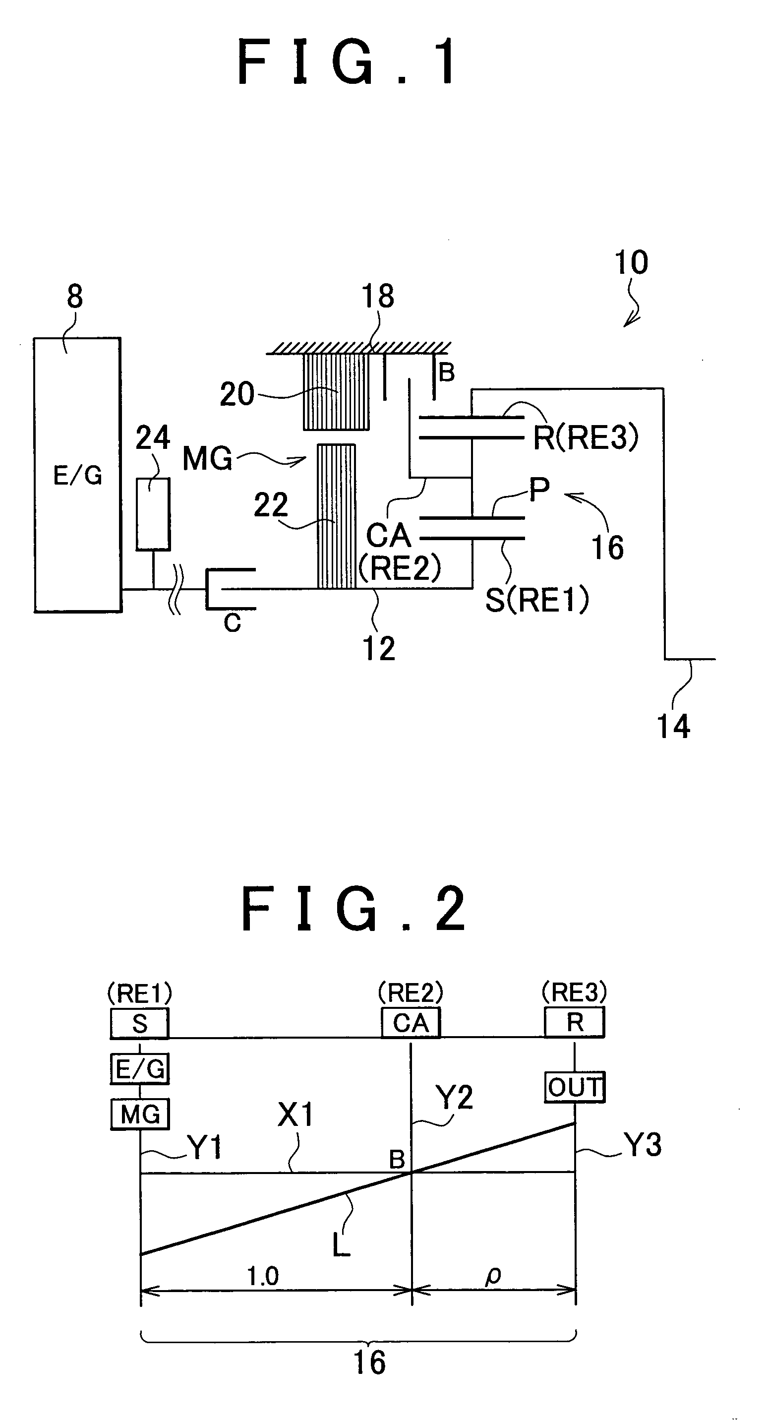
[0037]FIG. 1 is a skeleton diagram illustrating a basic construction that is a portion of a vehicle hybrid driving apparatus 10 in accordance with the invention. In FIG. 1, the vehicle hybrid driving apparatus 10 is constructed mainly of an input shaft 12, an electric motor MG that is linked to the input shaft 12 so that power transmission therebetween is possible, an output shaft 14 that is linked to driving wheels via a final speed reducer (not shown) or the like so that power can be transmitted to the driving wheels, and a planetary gear device 16 disposed between the input shaft 12 and the output shaft 14. The input shaft 12 is linked to an engine 8 via a clutch C so that power transmission therebetween is possible, and is also linked to the electric motor MG so that power transmission therebetween is possible. Thus, the vehicle hybrid driving apparatus 10 is able to selectively use the engine 8 and the electric motor MG as a drive power source. Incidentally, the engine 8 is mad...

second embodiment

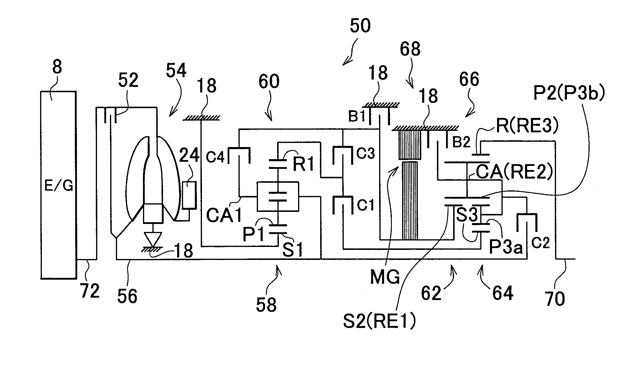
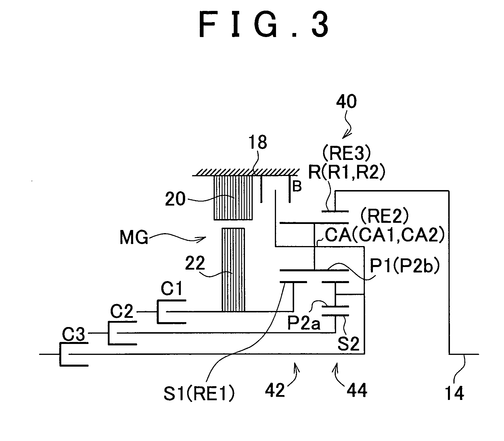
[0054]FIG. 3 is a skeleton diagram of a vehicle hybrid driving apparatus 40 in accordance with the invention, showing an example of a construction in which the foregoing vehicle hybrid driving apparatus 10 is combined with an automatic transmission capable of shifting to a plurality of speed change steps, or the like. The vehicle hybrid driving apparatus 40 shown in FIG. 3 has a first planetary gear device 42, and a second planetary gear device 44.

[0055]The first planetary gear device 42 is a single-pinion type planetary gear device that includes a first sun gear S1, first pinions P1, a first carrier CA1 that supports the first pinions P1 so that the first pinions P1 are rotatable about their own axes and revolvable about a common axis, and a first ring gear R1 that meshes with the first sun gear S1 via the first pinions P1. Besides, the second planetary gear device 44 is a double-pinion type planetary gear device that includes a second sun gear S2, two sets of second pinions P2 (P2...


PUM


Abstract

A vehicle hybrid driving apparatus that has an engine and an electric motor as drive power sources includes: a hydraulic pressure generation mechanism that generates hydraulic pressure using drive force from the engine; and a planetary gear ratio shift device that has three rotating elements: a first rotating element, a second rotating element, and a third rotating element. The first rotating element is linked to the electric motor so that power transmission therebetween is possible, and is also linked to the engine via a clutch so that power transmission therebetween is possible. The second rotating element is selectively linked to a stationary member via a brake. The third rotating element is linked to an output shaft so that power transmission therebetween is possible. The brake connects the second rotating element and the stationary member when the hydraulic pressure from the hydraulic pressure generation mechanism is not supplied.

Description

INCORPORATION BY REFERENCE[0001]The disclosure of Japanese Patent Application No. 2008-297632 filed on Nov. 21, 2008, including the specification, drawings and abstract is incorporated herein by reference in its entirety.BACKGROUND OF THE INVENTION[0002]1. Field of Invention[0003]The invention relates to a vehicle hybrid driving apparatus that has an engine and an electric motor as drive power sources, and particularly concerns size reduction of the power transmission device, and improvement in the fuel economy thereof.[0004]2. Description of Related Art[0005]There is known a driving apparatus for a hybrid vehicle whose drive power sources are an engine that is an internal combustion engine such as a gasoline engine, a diesel engine, etc., and an electric motor that is driven by electric energy. An example of such an apparatus is a hybrid driving apparatus (power transmission apparatus) described in Japanese Patent Application Publication No. 6-169504 (JP-A-6-169504). In the hybrid ...

Claims


Application Information

Patent Timeline
Patent Type & Authority Applications(United States)
IPC IPC(8): F16H3/72B60L50/16
CPCB60K6/365Y02T10/642B60K6/547B60L2240/423B60W10/02B60W10/08B60W20/00B60W2710/083F16H3/725F16H2200/0052F16H2200/0086F16H2200/2007F16H2200/2023F16H2200/2043F16H2200/2046F16H2200/2097Y02T10/6221B60K6/48Y02T10/62Y02T10/64B60W10/115B60W20/15
Inventor ETO, SHINGOMIYAMOTO, KOICHIKAMIYA, TOSHIHIKO
Owner TOYOTA JIDOSHA KK
Features
  • R&D
  • Intellectual Property
  • Life Sciences
  • Materials
  • Tech Scout
  • Unparalleled Data Quality
  • Higher Quality Content
  • 60% Fewer Hallucinations
Learn More