

Low power dehumidifier
a dehumidifier and low-power technology, applied in the field of dehumidifiers, can solve the problems of adding power consumption, high power consumption of conventional desiccant wheel dehumidifiers, etc., and achieve the effect of reducing power consumption and efficient recycling of waste high hea
- Summary
- Abstract
- Description
- Claims
- Application Information
AI Technical Summary
Benefits of technology
Problems solved by technology
Method used
Image

Examples
first preferred embodiment
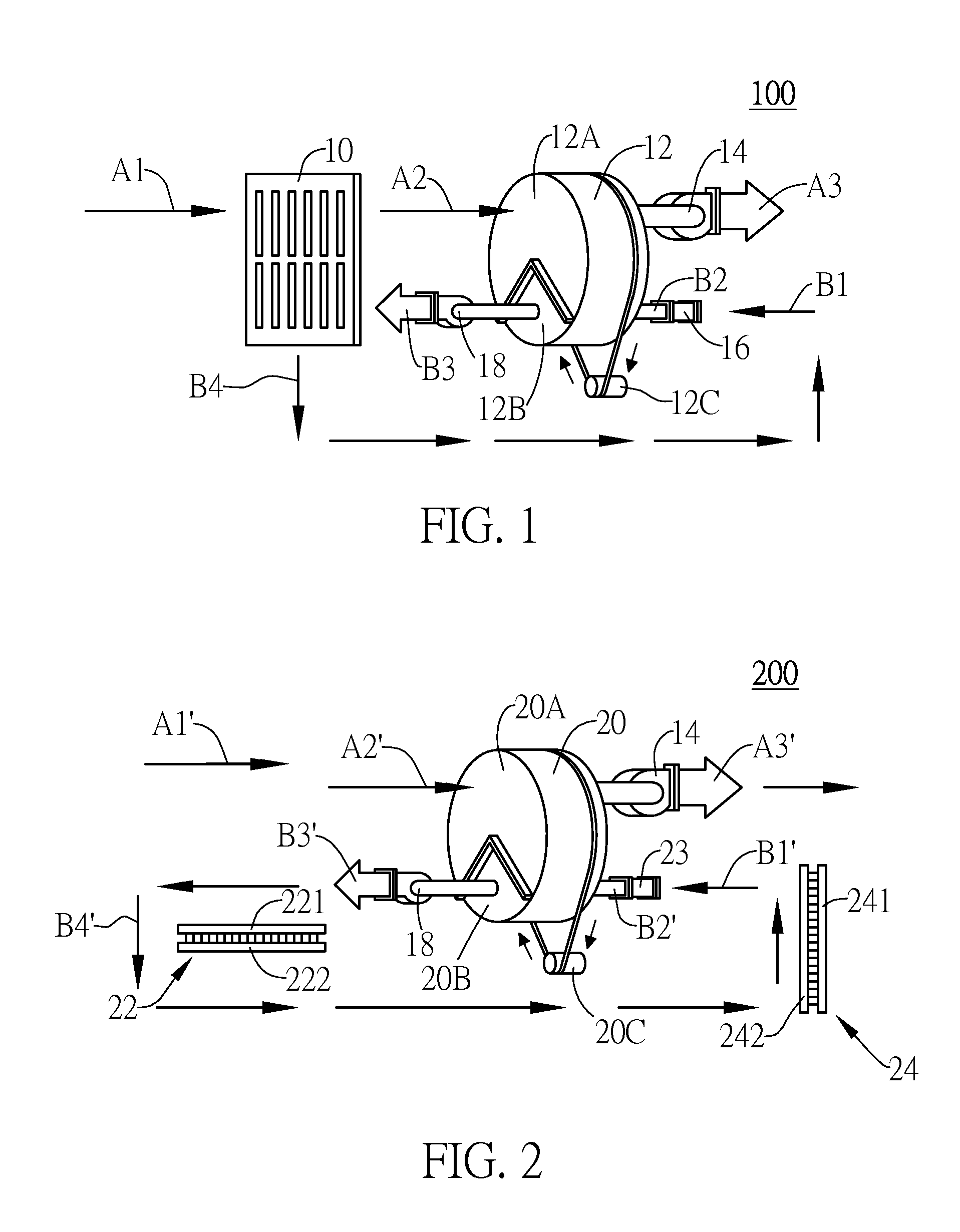
[0027]FIG. 2 is a schematic view of a first preferred embodiment of a low power dehumidifier of the present invention. For the sake of conciseness, heat transfer elements of the present invention are exemplified by at least a thermoelectric cooler (TEC) as shown in FIG. 2, but the present invention is not limited thereto. As shown in FIG. 2, a low power dehumidifier of the present invention comprises: a body 200, a desiccant wheel 20, thermoelectric coolers 22, 24 (that is, heat transfer elements), and an electric heater 23. The thermoelectric coolers 22, 24 have cooling ends 221, 241 and heating ends 222, 242, respectively. Specifically speaking, the thermoelectric coolers 22, 24 each comprise p-type and n-type semiconductor elements and a conventional conductor interposed therebetween so as to form a complete circuit. Heat exchange takes place between the cooling ends 221, 241 and the heating ends 222, 242 due to current-induced temperature difference (Peltier Effect) or temperatu...
second preferred embodiment
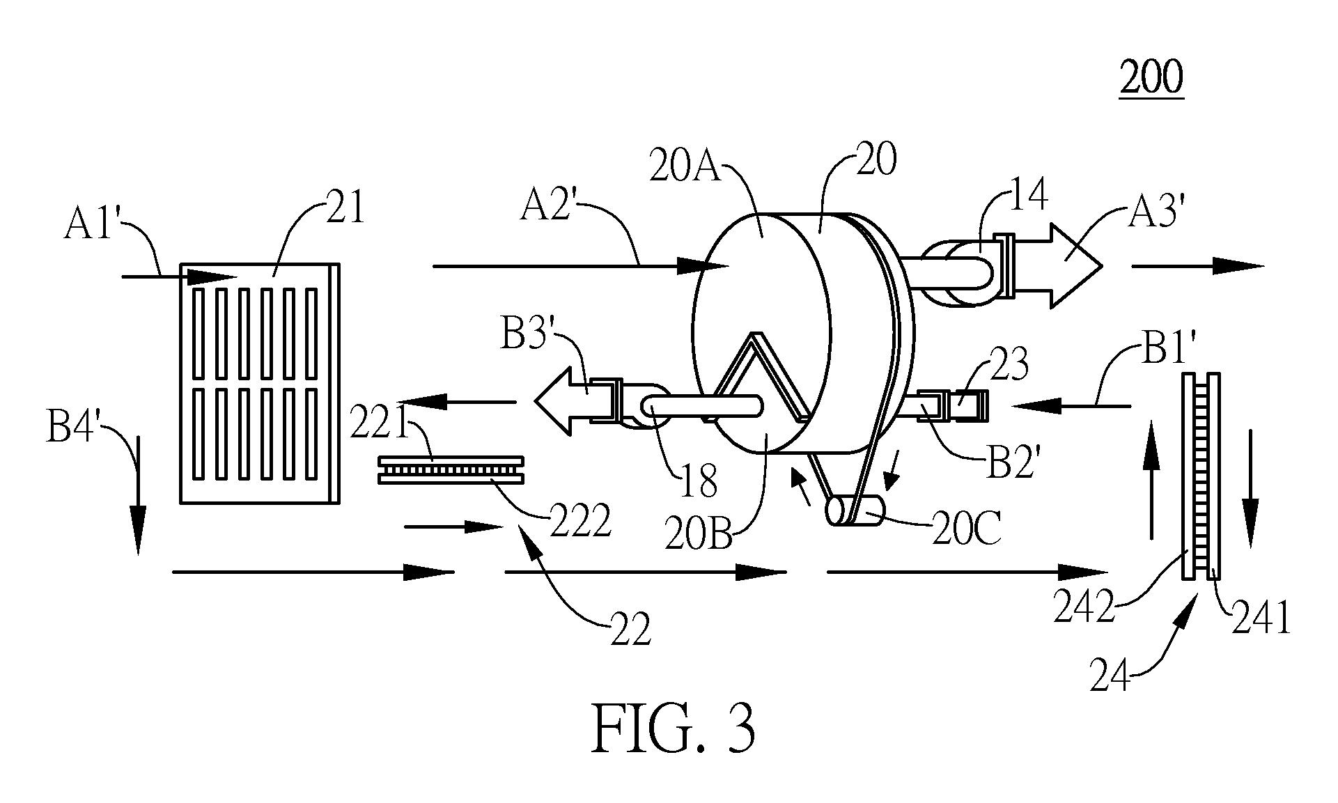
[0030]Referring to FIG. 3, a schematic view of a second preferred embodiment of the low power dehumidifier of the present invention is shown. The second preferred embodiment differs from the first preferred embodiment in that, in the second preferred embodiment, the low power dehumidifier further comprises a heat exchanger 21. As shown in the drawing, after passing through the heat exchanger 21, humid ambient air is delivered to the dehumidifying region 20A of the desiccant wheel 20. Also, as shown in the drawing, after being treated by the thermoelectric cooler 22, the humid hot air B2′ is introduced into the heat exchanger 21 via the condensing regions B3′, B4′ of the second channel so as for the humid hot air B2′ to be cooled down by the heat exchanger 21 and the water vapor in the humid hot air B2′ to be condensed. Then, condensed water is delivered to a container (not shown) at the bottom of the body 200 of the dehumidifier via B3′ and B4′ of the second channel, wherein the con...
third preferred embodiment
[0032]Referring to FIG. 4, a schematic view of a third preferred embodiment of the low power dehumidifier of the present invention is shown. As shown in the drawing, the third preferred embodiment differs from the first preferred embodiment in that, in the third preferred embodiment, a heat transfer element is provided in the form of a refrigeration cycle system instead of the thermoelectric coolers 22, 24. As shown in the drawing, the refrigeration cycle system comprises a compressor 260, a first condenser 261, a second condenser 262, an expansion valve 264, and an evaporator 266, and receives a working fluid L, such as a coolant, passing through the refrigeration cycle system. The body 300 is internally provided with a first channel (marked with arrows indicated by A1′ through A3′) for taking in humid ambient air A1′ and a second channel (marked with arrows indicated by B1′ through B6′) composed of heating regions B1′, B2′, B5′, B6′ and condensing regions B3′, B4′. A heat exchange...
PUM
 Abstract
Description
Claims
Application Information