Expandable Energy Storage Control System Architecture

a control system and expansion technology, applied in the direction of machine/engine, process and machine control, vehicle sub-unit features, etc., can solve the problems of inability to receive the entire amount of electricity, energy storage units often need to be oversized, and heavy-duty hevs face unique challenges. , to achieve the effect of reliable, efficient and inexpensiv

Inactive Publication Date: 2010-06-03
SHEPPARD MULLIN RICHTER & HAMPTON
View PDF10 Cites 110 Cited by
  • Summary
  • Abstract
  • Description
  • Claims
  • Application Information

AI Technical Summary

Benefits of technology

[0008]The disclosure relates to an efficient, inexpensive, and reliable architecture blending a battery-based energy storage with an ultracapacitor-based energy storage. In particular, the architecture includes a multi-level DC / DC converter topology that can independently operate on multiple DC-Buses and power sources having the intrinsic capability to operate in parallel to capture and conduit regenerative energy among multiple power and energy sources.

Problems solved by technology

Moreover, unlike stationary hybrid systems and even automotive HEVs, heavy duty HEVs face unique challenges associated with their substantially higher power levels, the mobile environment under substantially higher loads, increased safety requirements, and increased performance and duty cycle requirements.
While various energy storage technologies are available, the choice typically represents compromises between desired power density and desired energy density.
Accordingly, during a regenerative braking period, an ultracapacitor may be able to store all the electricity produced during one braking period, but this might use up all the ultracapacitors capacity; while a battery may be able to receive charge during many braking periods, but may not be able to receive the entire amount of electricity produced during one braking period.
Typically, regardless of the choice of technology, the energy storage unit will often need to be oversized to meet all of the vehicle's performance requirements.
As a practical matter though, the DC / DC converter may face unique challenges and be limited in its performance and capacity to buck or boost voltages.
However, IGBT (or similar) DC / DC converters may be have certain drawbacks in this application.
However, IGBT's are limited in their switching frequency (e.g., 20 kHz).
As a result of this limitation voltage ripple is increased at the higher frequencies and power quality is reduced.
In addition, IGBT's emit heat at high switching frequencies and become less efficient.
In a heavy duty hybrid application, these challenges may more pronounced.
Thus, in either type of HEV, at low energy storage SOC, the voltage step is substantial, and undesirable losses and noise are introduced.
Thus, in current hybrid drive systems, additional and / or high performance equipment, which is often expensive, may be required to meet these high voltage ratio and propulsion power requirements.

Method used


Image

  • Expandable Energy Storage Control System Architecture
  • Expandable Energy Storage Control System Architecture
  • Expandable Energy Storage Control System Architecture

Examples


Embodiment Construction

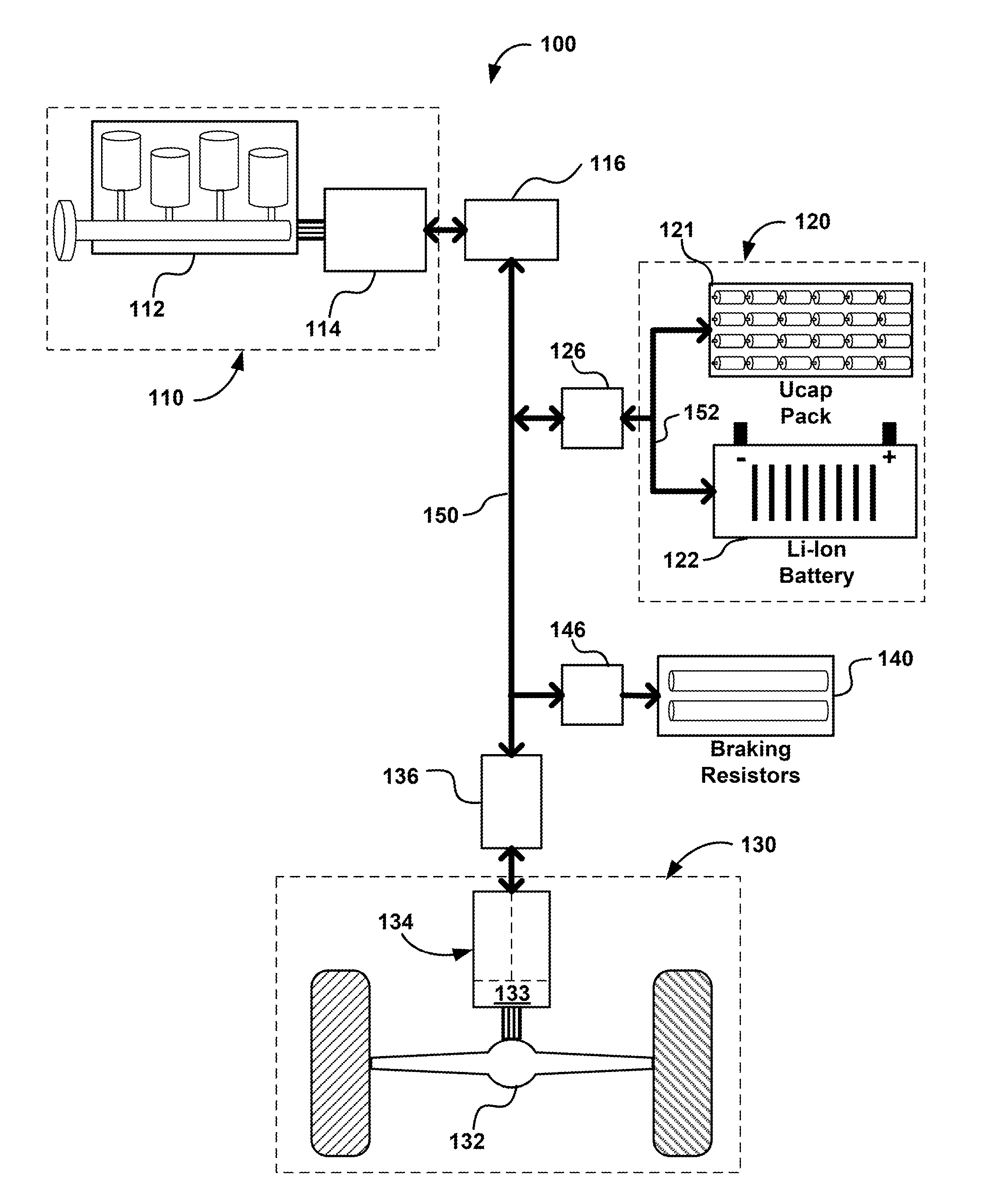
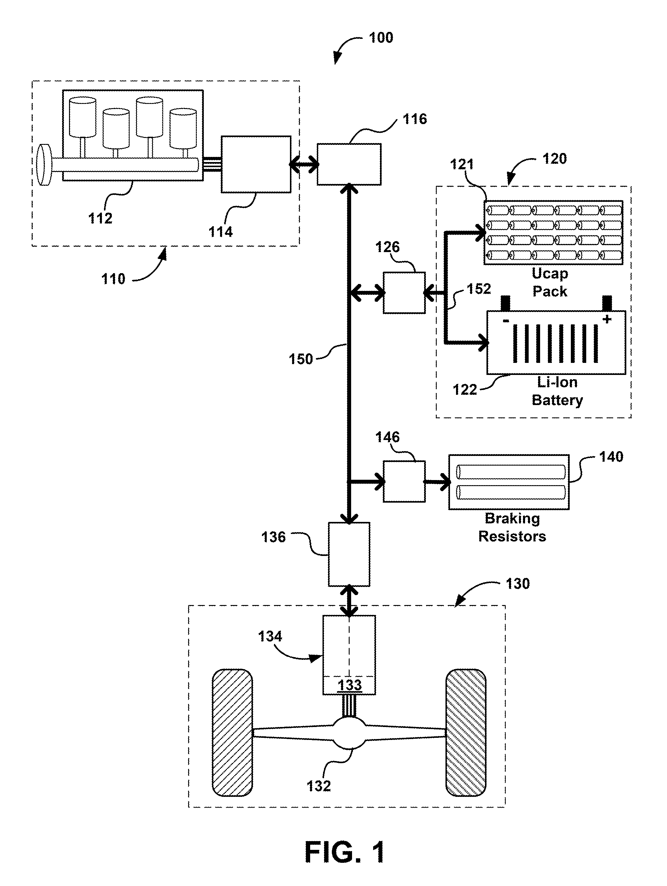
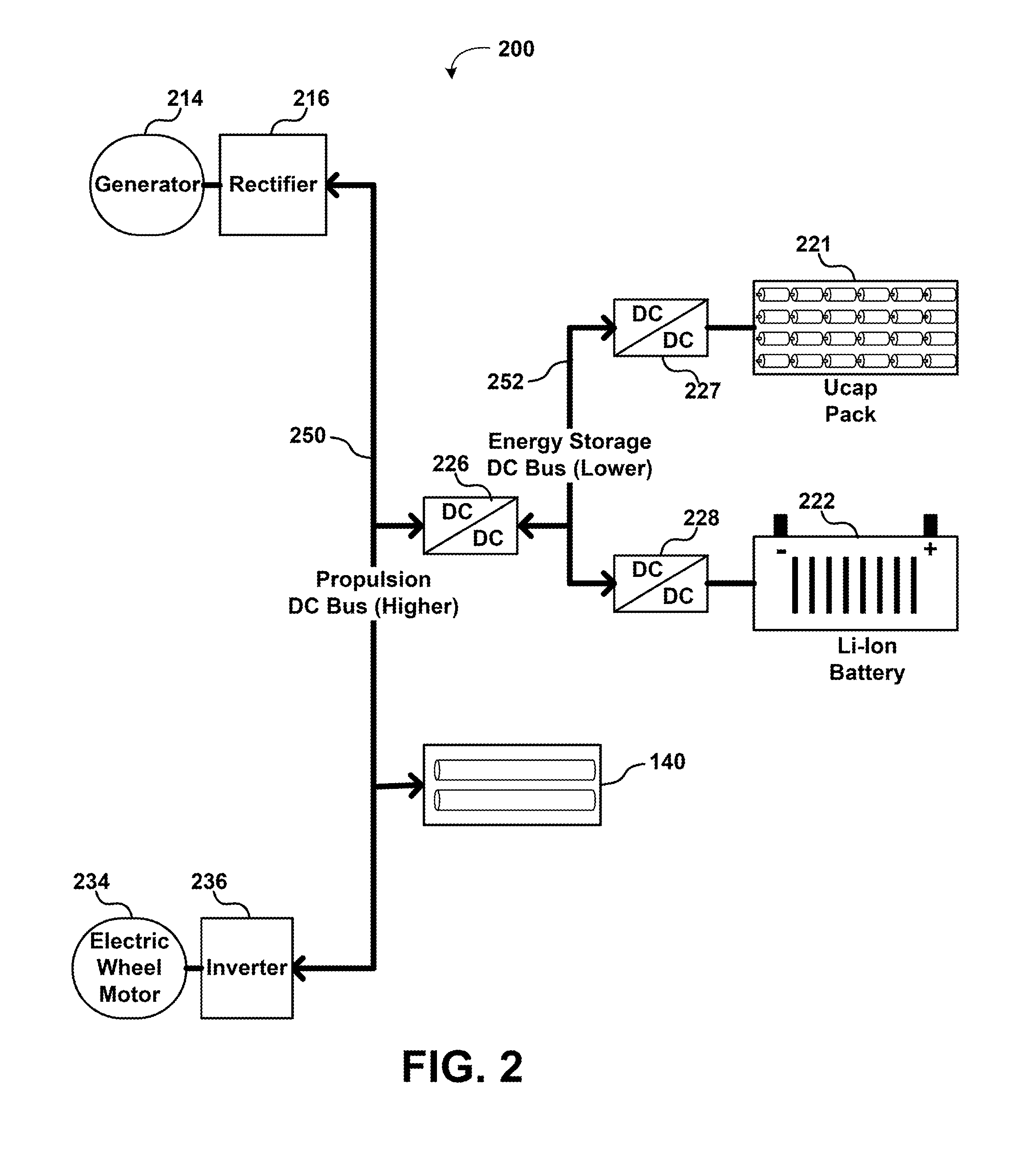
[0021]Referring to FIG. 1, depicting a drive system 100 of a hybrid electric vehicle (HEV), the various vehicle subsystems are coupled to a common electrical bus 150. The HEV drive system 100 may include multiple energy sources, such as a motive energy subsystem 110, an energy storage subsystem 120, and a drive wheel propulsion assembly 130 in a regenerative braking mode (“regen”).

[0022]Motive energy subsystem 110 may comprise power generating components that serve as the ultimate source for motive power for the vehicle. For example, a motive energy subsystem may comprise an internal combustion engine (ICE) or a compressed air engine coupled to a generator, a fuel cell, or, in a fully electric vehicle, and a large capacity electric storage system. In the illustrated embodiment, the motive energy subsystem 110 comprises an internal combustion engine 112 mechanically coupled to an electrical generator 114. A variety of internal combustion engines and electrical generators may be used ...


PUM


Abstract

A hybrid electric vehicle drive system comprises a first power bus electrically coupled to a motive power subsystem and a drive wheel propulsion assembly; a second power bus electrically coupled to the first power bus and a plurality of energy storage subsystems, wherein the first power bus is configured to allow electrical power to be transmitted among the motive power subsystem, the drive wheel propulsion assembly, and the second power bus, and wherein the second power bus is configured to allow electrical power to be transmitted among the plurality of energy storage subsystems and the first power bus.

Description

FIELD OF THE INVENTION[0001]The present invention relates generally to motor vehicles, and more particularly, hybrid electric vehicles (HEVs) wherein an electric motor in the body or on the body-frame drives the vehicle. The present invention includes subject matter having a specific or particular functional arrangement of or interconnection between two or more major components (e.g., wheel, motor / generator, engine, etc.) of a drive train. Some embodiments relate to a vehicle having an arrangement for control of an individual subunit (i.e., energy storage) of a hybrid electric power train.BACKGROUND OF THE INVENTION[0002]Typical hybrid electric vehicles (HEVs) use combinations of energy sources to provide motive power to a vehicle. In some serial HEVs, an internal combustion engine is used to power an electric generator, whereby electricity from the generator is then used to power an electric motor that is used to drive the vehicle. The electricity from the generator may also be use...

Claims


Application Information

Patent Timeline
Patent Type & Authority Applications(United States)
IPC IPC(8): B60K6/42B60W20/00B60W10/26B60L9/00
CPCB60K6/46B60Y2400/114B60L7/14B60L7/22B60L11/005B60L11/123B60L11/1868B60W10/26B60W20/00B60W30/18127B60Y2200/14H02J1/102H02J7/1423H02J7/1438H02J7/345H02J2007/0062Y02T10/6217Y02T10/6278Y02T10/7005Y02T10/7022Y02T10/7066Y02T10/7077B60K6/28B60L7/06F02N11/0866F02N2011/0885F02N2011/0888F02N2011/0896B60L50/40B60L50/61B60L58/20Y02T10/62Y02T10/70B60K6/42B60W20/15B60W10/24H02J7/00Y02T10/7072
Inventor FLETT, FREDERICK P.
Owner SHEPPARD MULLIN RICHTER & HAMPTON
Why Eureka
Try Eureka