Magnetic resonance imaging system and method

a magnetic resonance imaging and magnetic resonance technology, applied in the field of magnetic resonance imaging apparatus, can solve the problems of inability to obtain accurate real-time component images, generation of spatial distribution of phase variation (phase error distribution), etc., and achieve the effect of high accuracy

Active Publication Date: 2010-06-03
FUJIFILM HEALTHCARE CORP
View PDF5 Cites 6 Cited by
  • Summary
  • Abstract
  • Description
  • Claims
  • Application Information

AI Technical Summary

Benefits of technology

[0028]In accordance with the present invention, it is possible to obtain a real component image with high accuracy by correcting spatial phase variation of NMR signals.BRIEF DESCRIPTION OF THE DIAGRAMS
[0029]FIG. 1 is a block diagram showing a general configuration of the MRI apparatus of the present embodiment.
[0030]FIG. 2 is a flowchart showing the imaging operation of a real component image by the MRI apparatus in FIG. 1.
[0031]FIG. 3 is a flowchart showing the imaging operation of a real component image by the MRI apparatus in FIG. 1.
[0032]FIG. 4 is an explanatory diagram showing a pulse sequence for phase correction data to be used in the procedure of FIG. 3.
[0033]FIG. 5 is an explanatory diagram showing a pulse sequence for image acquisition data to be used in the procedure of FIG. 3.

Problems solved by technology

However, generation of spatial distribution of phase variation (phase error distribution) occurs in the measured NMR signals attributed to the apparatuses or environment such as inhomogeneity of the static magnetic field in the imaging space or inhomogeneity of the readout gradient magnetic field.
As a result, even though the phase of the measurement for image acquisition is corrected by using a reference phase data obtained by setting the phase encode as zero and the images of only a real component in the respective channels are synthesized using the technique disclosed in Patent Document 1, since the phase error distribution by the respective reception coils can not be corrected, accurate real component images can not be obtained.

Method used


Image

  • Magnetic resonance imaging system and method
  • Magnetic resonance imaging system and method
  • Magnetic resonance imaging system and method

Examples


embodiment 1

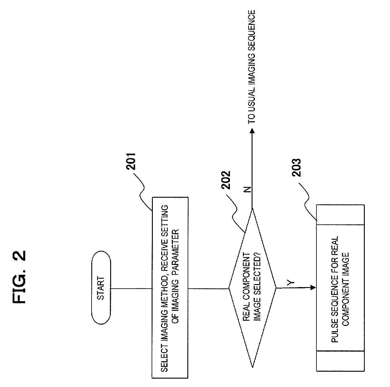
[0049]Next, the method for imaging real component images using the MRI apparatus of the present embodiment will be described referring to FIG. 2-FIG. 5. As an imaging method, the pulse sequence (imaging method) for obtaining real component images by the IR method for applying inversion recovery (IR) pulses is to be used. Any sequence such as spin echo sequence or gradient echo sequence may be used for collecting the NMR signals by which the pulse sequences are formed. In the embodiment below, the imaging method for collecting echo signals by high-speed spin echo sequence after applying IR pulses will be exemplified.

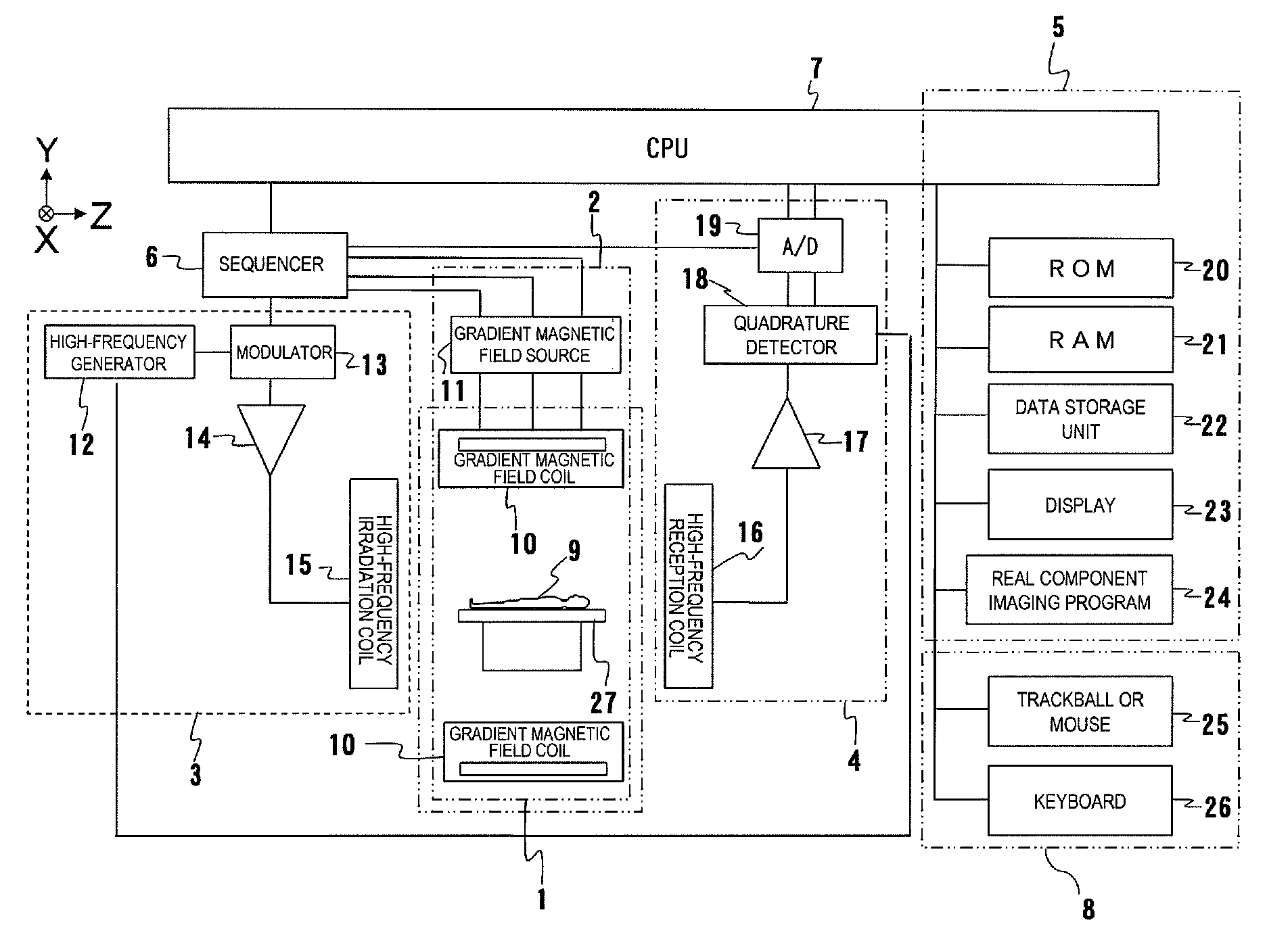
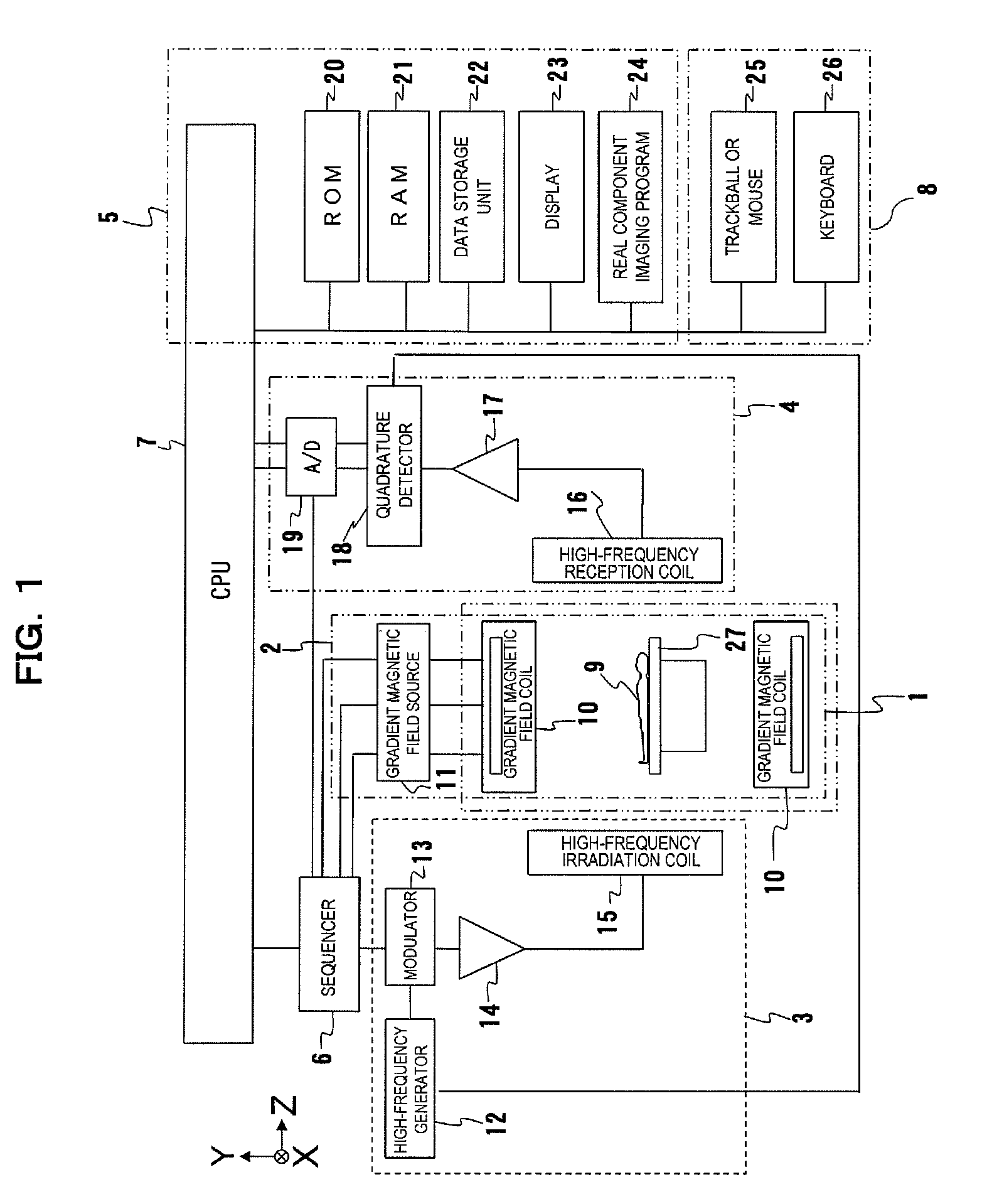
[0050]In real component imaging program storage unit 24 of the signal processing system in the MRI apparatus, the program for executing the operation in the flowcharts shown in FIG. 2 and FIG. 3 is stored. CPU 7 carries out imaging or reconstruction operation as will be described below by reading and executing the stored program.

[0051]First, the flowchart in FIG. 2 will b...


PUM


Abstract

A magnetic resonance imaging system is characterized in that a control unit executes, as pulse sequences, a first sequence for obtaining data of a predetermined 2-dimensional region in a k-space and a second sequence for obtaining data required for reconstruction of an image by irradiating an object to be examined with an inversion recovery pulse and corrects the phase of the data obtained by the second sequence with the data of the 2-dimensional region obtained by the first sequence, and in that a signal processing unit reconstructs a real component image with corrected data.Upon execution of the first sequence, the control unit obtains the data of the predetermined 2-dimensional region in the k-space while varying a phase encoding amount.

Description

TECHNICAL FIELD[0001]The present invention relates to a magnetic resonance imaging apparatus (hereinafter referred to as an MRI apparatus) and method, particularly to the MRI apparatus and method for obtaining a real component image using the inversion recovery method that applies an inversion recovery pulse (IR pulse) before acquiring image data.BACKGROUND ART[0002]Magnetic resonance imaging apparatuses irradiate high-frequency magnetic pulses in the condition that an object to be examined is placed in a homogeneous magnetic field to excite atomic nuclei such as hydrogen in the living body, and measure nuclear magnetic resonance signals (NMR signals) produced by the excitation. Then the measurement regions in the living body are to be imaged and displayed based on the magnetic resonance information such as the density distribution of the measured signals or distribution of relaxation time thereof, to be used for purposes such as medical diagnosis.[0003]Such MRI apparatuses can obta...

Claims


Application Information

Patent Timeline
Patent Type & Authority Applications(United States)
IPC IPC(8): G01R33/48
CPCG01R33/5602G01R33/5607G01R33/5615G01R33/5659G01R33/565G01R33/56563G01R33/56572G01R33/5617
Inventor KITAMOTO, NAOYA
Owner FUJIFILM HEALTHCARE CORP
Why Eureka
Try Eureka