Piezoelectric Resonator and Piezoelectric Filter Device

a piezoelectric filter and piezoelectric resonator technology, applied in the direction of impedence networks, electrical devices, etc., can solve the problems of inability to achieve good resonant properties or filter properties, and achieve the effect of reducing the wiring resistance of the second electrode, improving the insertion loss, and reducing thickness

Inactive Publication Date: 2010-06-03
MURATA MFG CO LTD
View PDF12 Cites 41 Cited by
  • Summary
  • Abstract
  • Description
  • Claims
  • Application Information

AI Technical Summary

Benefits of technology

[0018]In the piezoelectric filter device, the thickness of the second electrode of at least one of the piezoelectric resonators is preferably different from the thickness of the second electrode of each of the other piezoelectric resonators such that the resonant frequency of at least one of the piezoelectric resonators is different from the resonant frequency of each of the other piezoelectric resonators. The thickness of the second electrode of at least one of the piezoelectric resonators can be readily adjusted to be different from the thickness of the second electrode of each of the other piezoelectric resonators and therefore the resonant frequency of at least one of the piezoelectric resonators can be readily adjusted to be different from the resonant frequency of each of the other piezoelectric resonators.
[0019]In the piezoelectric filter device, the first electrode and second electrode of at least one of the piezoelectric resonators are preferably different in thickness from each other. Furthermore, the thickness of the second electrode of at least one of the piezoelectric resonators is preferably greater than the thickness of the first electrode thereof. In this case, the wiring resistance of the second electrode can be reduced and therefore insertion loss can be improved.
[0020]In a piezoelectric resonator according to the present invention, an energy confini

Problems solved by technology

However, a spurious component is likely to be caused by a Lamb wave, other than the thickness longitudinal vibration mode, propagating in

Method used


Image

  • Piezoelectric Resonator and Piezoelectric Filter Device
  • Piezoelectric Resonator and Piezoelectric Filter Device
  • Piezoelectric Resonator and Piezoelectric Filter Device

Examples


first embodiment

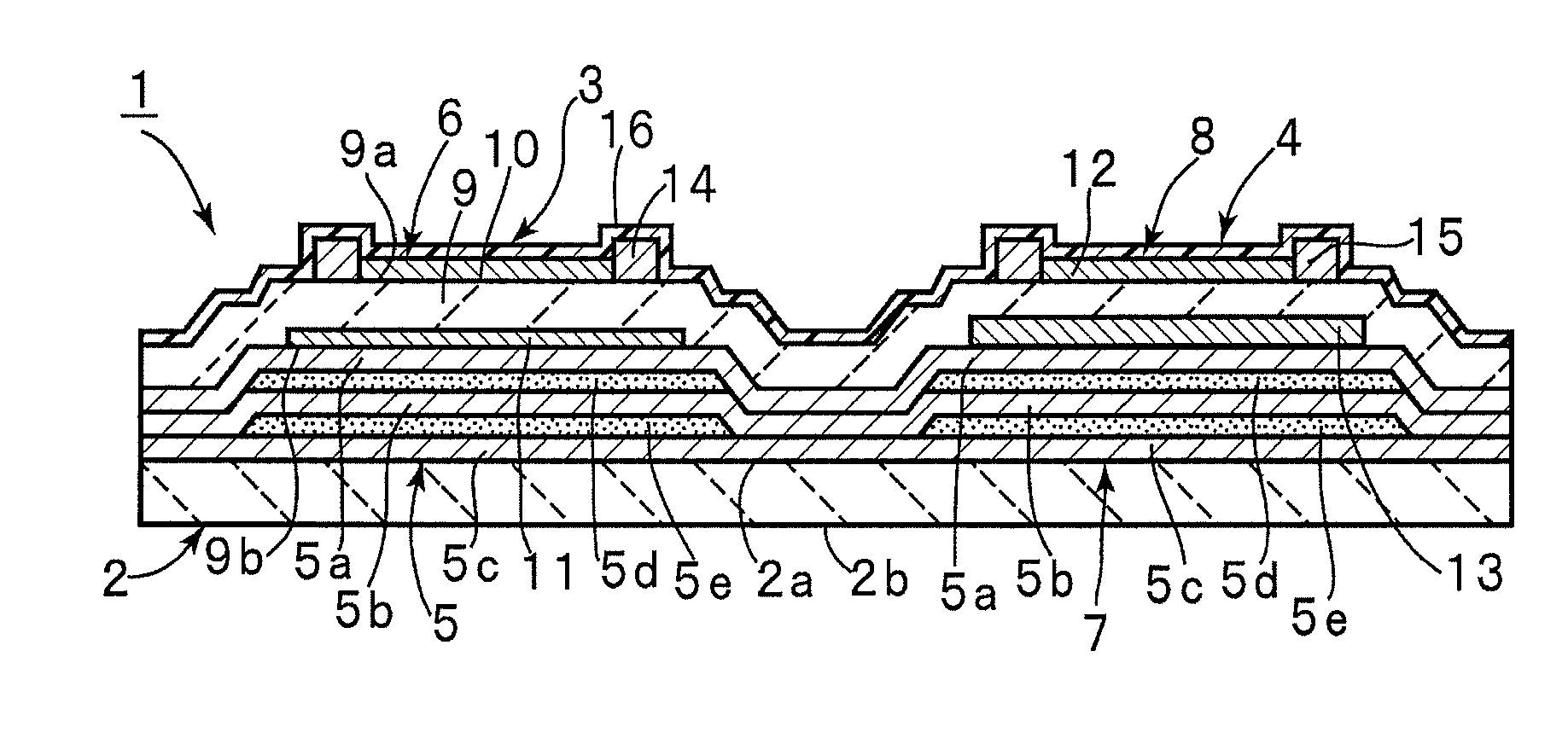
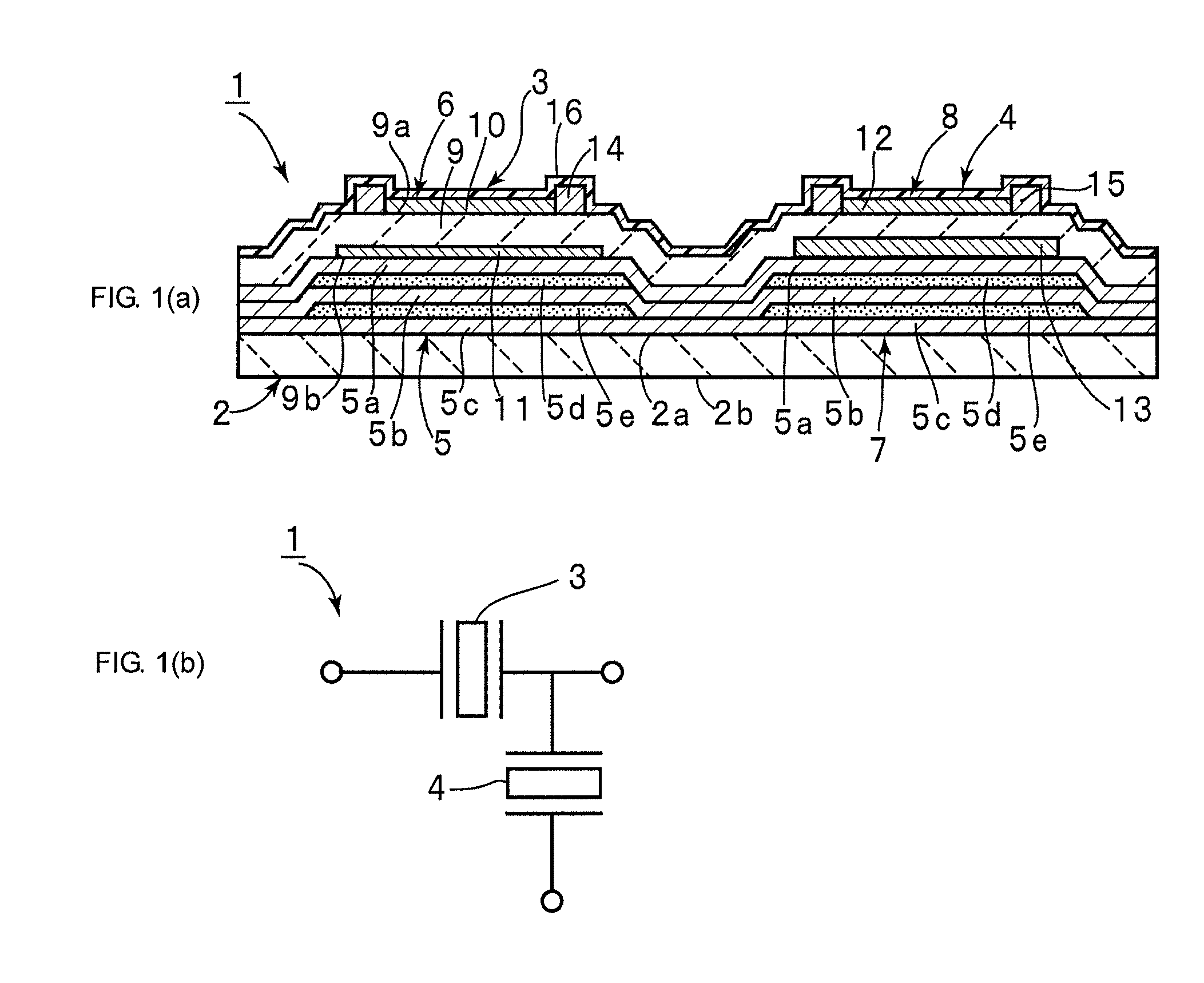
[0084]FIG. 1 is a front sectional view of a piezoelectric filter device according to a first embodiment of the present invention. The piezoelectric filter device 1 includes a substrate 2. The substrate 2 has an upper surface 2a that is a first principal surface and a lower surface 2b that is a second principal surface.

[0085]The substrate 2 is made of an appropriate insulating material. In particular, the substrate 2 is made of a semiconductor material such as Si, GaAs, GaN, or SiC; an insulating ceramic such as glass, alumina, sapphire, quartz, lithium tantalate, or lithium niobate; or a single-crystalline insulating resin. In this embodiment, the substrate 2 is made of high-resistivity Si (with a resistivity of 1000 Ω·cm or more).

[0086]In this embodiment, the single substrate 2 carries a plurality of piezoelectric resonators 3 and 4. That is, the substrate 2 is common to the piezoelectric resonators 3 and 4. The piezoelectric resonators 3 and 4 may be disposed above different subst...

second embodiment

[0134]A piezoelectric filter device according to a second embodiment of the present invention has substantially the same configuration as that of the piezoelectric filter device 1 except that materials for forming members and the thickness of each member are as shown in Table 2. Since the piezoelectric filter device according to the second embodiment has substantially the same configuration as that of the piezoelectric filter device 1 according to the first embodiment, the same reference numerals as those described in the first embodiment are used for description.

TABLE 2Thickness of each layer of resonators (nm)PiezoelectricPiezoelectricresonator 3resonator 4Protective / frequency-adjusting100100film, SiO2Adding film, AlN850850Upper electrode, Al / W200 / 150200 / 150Piezoelectric film, AlN12001200Lower electrode, W / Al150 / 200150 / 200Low-acoustic impedance layer,820820SiO2High-acoustic impedance690690layer, WLow-acoustic impedance layer,820820SiO2High-acoustic impedance690690layer, WLow-acous...

third embodiment

[0137]A piezoelectric filter device 1 was obtained in substantially the same manner as that described in the first embodiment except that materials for forming members and the thickness of each member were as shown in Table 3 below.

TABLE 3Thickness of each layer of resonators (nm)PiezoelectricPiezoelectricresonator 3resonator 4Protective / frequency-100100adjusting film, SiO2Adding film, AlN500500Upper electrode,100 / 10 / 60 / 10100 / 10 / 60 / 10Al / Ti / Pt / TiPiezoelectric film, AlN11851185Lower electrode,10 / 60 / 10 / 100 / 1010 / 60 / 10 / 200 / 10Ti / Pt / Ti / Al / TiLow-acoustic impedance600600layer, SiO2High-acoustic impedance500500layer, WLow-acoustic impedance600600layer, SiO2High-acoustic impedance500500layer, WLow-acoustic impedance600600layer, SiO2High-acoustic impedance500500layer, WLow-acoustic impedance600600layer, SiO2Resonant frequency (MHz)253924681-pF equivalent area (μm2)1282012820

[0138]The first piezoelectric resonator 3 serves as a series arm resonator and has a design resonant frequency of 2539 MHz...


PUM


Abstract

A piezoelectric resonator includes an acoustic reflective layer including first acoustic impedance sub-layers made of a material with relatively low acoustic impedance and second acoustic impedance sub-layers made of a material with relatively high acoustic impedance. A thin-film laminate is disposed on the acoustic reflective layer. The thin-film laminate includes a piezoelectric thin-film, a first electrode, a second electrode greater than the first electrode, and a mass-adding film. The second electrode is disposed on the acoustic reflective layer. The mass-adding film is disposed in at least one portion of a region outside a piezoelectric vibrational section and extends around the first electrode. The second electrode extends over the piezoelectric vibrational section to a region containing the mass-adding film.

Description

CROSS REFERENCE TO RELATED APPLICATIONS[0001]The present application is a continuation of International Application No. PCT / JP2008 / 060131, filed Jun. 2, 2008, and claims priority to Japanese Patent Application No. JP2007-189901, filed Jul. 20, 2007, the entire contents of each of these applications being incorporated herein by reference in their entirety.FIELD OF THE INVENTION[0002]The present invention relates to piezoelectric resonators for use in, for example, oscillators, band-pass filters, and the like and also relates to piezoelectric filter devices. The present invention particularly relates to a piezoelectric resonator including a substrate and a thin-film laminate which includes a first electrode, a second electrode, and a piezoelectric thin-film disposed therebetween and which is disposed on the substrate and also relates to a piezoelectric filter device.BACKGROUND OF THE INVENTION[0003]Conventional piezoelectric resonators and piezoelectric filter devices are known to inc...

Claims


Application Information

Patent Timeline
IPC IPC(8): H03H9/205H03H9/17H01L41/22H01L41/29H01L41/39
CPCH03H3/04H03H9/105H03H9/175H03H2003/0471H03H2003/025H03H2003/0414H03H9/564
Inventor UMEDA, KEIICHI
Owner MURATA MFG CO LTD
Why Eureka
Try Eureka