
Cell Separator for Minimizing Thermal Runaway Propagation within a Battery Pack

a cell separator and battery pack technology, applied in the field of batteries, can solve the problems of secondary cells that often require special handling during fabrication, the type of batteries is not without its drawbacks, and the risk of thermal runaway propagation is reduced, so as to minimize the thermal effect of adjacent cells and reduce the risk of thermal runaway propagation

Active Publication Date: 2010-06-03
TESLA INC
View PDF3 Cites 38 Cited by
  • Summary
  • Abstract
  • Description
  • Claims
  • Application Information

AI Technical Summary

Benefits of technology

[0006]The present invention provides a spacer assembly for use with a cell mounting bracket in a battery pack. The spacer assembly, comprised of one or more spacers, maintains the positions of the batteries within the battery pack during a thermal event and after the cell mounting bracket loses structural integrity due to the increased temperature associated with the thermal event. By keeping the battery undergoing thermal runaway in its predetermined location within the battery pack, the minimum spacing between cells is maintained, thereby helping to minimize the thermal effects on adjacent cells while ensuring that the cooling system, if employed, is not compromised. As a result, the risk of thermal runaway propagation is reduced.

Problems solved by technology

Although rechargeable batteries offer a number of advantages over disposable batteries, this type of battery is not without its drawbacks.
In general, most of the disadvantages associated with rechargeable batteries are due to the battery chemistries employed, as these chemistries tend to be less stable than those used in primary cells.
Due to these relatively unstable chemistries, secondary cells often require special handling during fabrication.
Additionally, secondary cells such as lithium-ion cells tend to be more prone to thermal runaway than primary cells, thermal runaway occurring when the internal reaction rate increases to the point that more heat is being generated than can be withdrawn, leading to a further increase in both reaction rate and heat generation.
Thermal runaway may be initiated by a short circuit within the cell, improper cell use, physical abuse, manufacturing defects, or exposure of the cell to extreme external temperatures.
Thermal runaway is of major concern since a single incident can lead to significant property damage and, in some circumstances, bodily harm or loss of life.
When a battery undergoes thermal runaway, it typically emits a large quantity of smoke, jets of flaming liquid electrolyte, and sufficient heat to lead to the combustion and destruction of materials in close proximity to the cell.
If the cell undergoing thermal runaway is surrounded by one or more additional cells as is typical in a battery pack, then a single thermal runaway event can quickly lead to the thermal runaway of multiple cells which, in turn, can lead to much more extensive collateral damage.
Regardless of whether a single cell or multiple cells are undergoing this phenomenon, if the initial fire is not extinguished immediately, subsequent fires may be caused that dramatically expand the degree of property damage.
For example, the thermal runaway of a battery within an unattended laptop will likely result in not only the destruction of the laptop, but also at least partial destruction of its surroundings, e.g., home, office, car, laboratory, etc.
If the laptop is on-board an aircraft, for example within the cargo hold or a luggage compartment, the ensuing smoke and fire may lead to an emergency landing or, under more dire conditions, a crash landing.
Similarly, the thermal runaway of one or more batteries within the battery pack of a hybrid or electric vehicle may destroy not only the car, but may lead to a car wreck if the car is being driven or the destruction of its surroundings if the car is parked.
Although this research may lead to improved cell chemistries and cell designs, currently this research is only expected to reduce, not eliminate, the possibility of thermal runaway.

Method used


Image

  • Cell Separator for Minimizing Thermal Runaway Propagation within a Battery Pack
  • Cell Separator for Minimizing Thermal Runaway Propagation within a Battery Pack
  • Cell Separator for Minimizing Thermal Runaway Propagation within a Battery Pack

Examples


Embodiment Construction

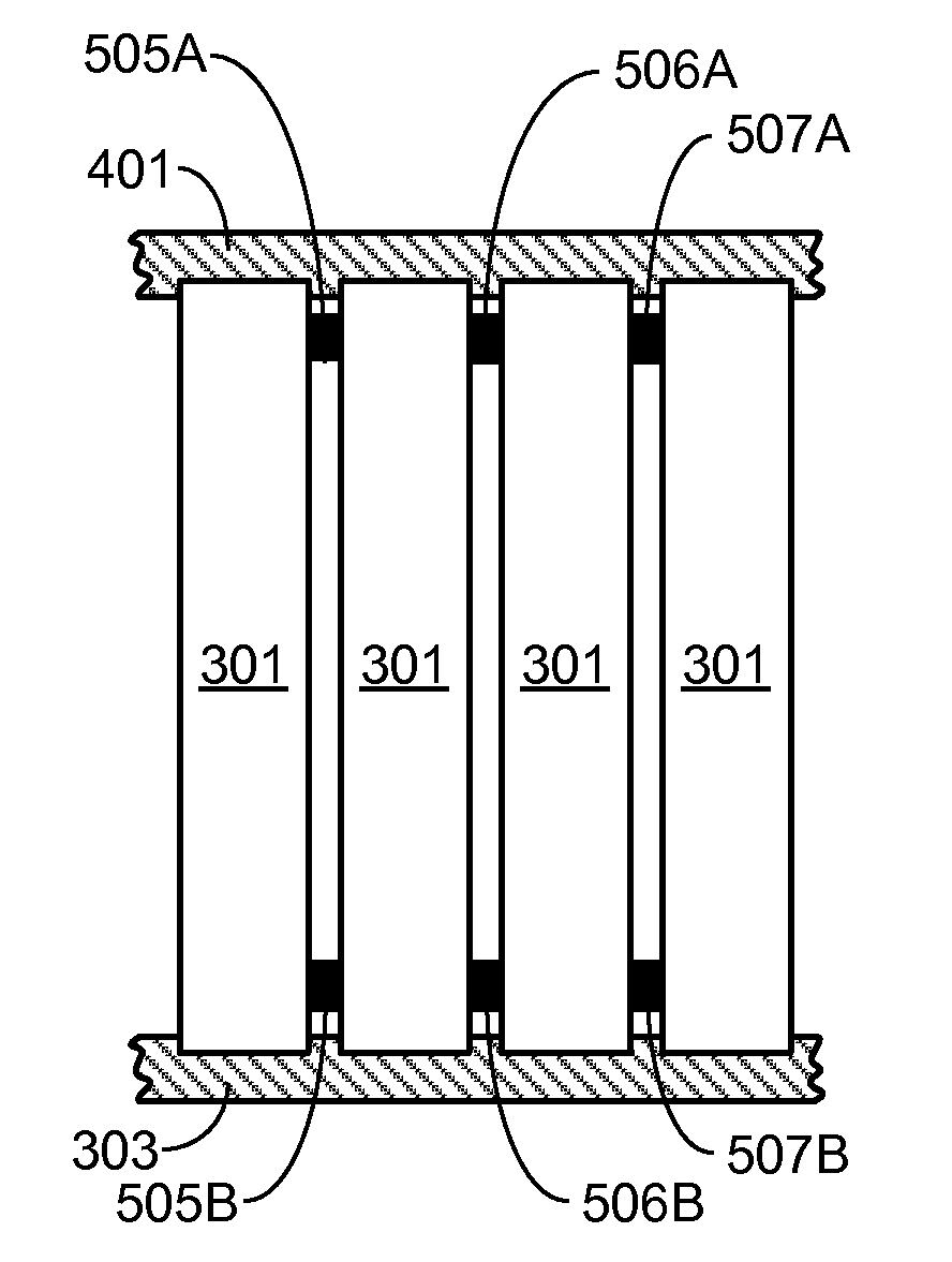
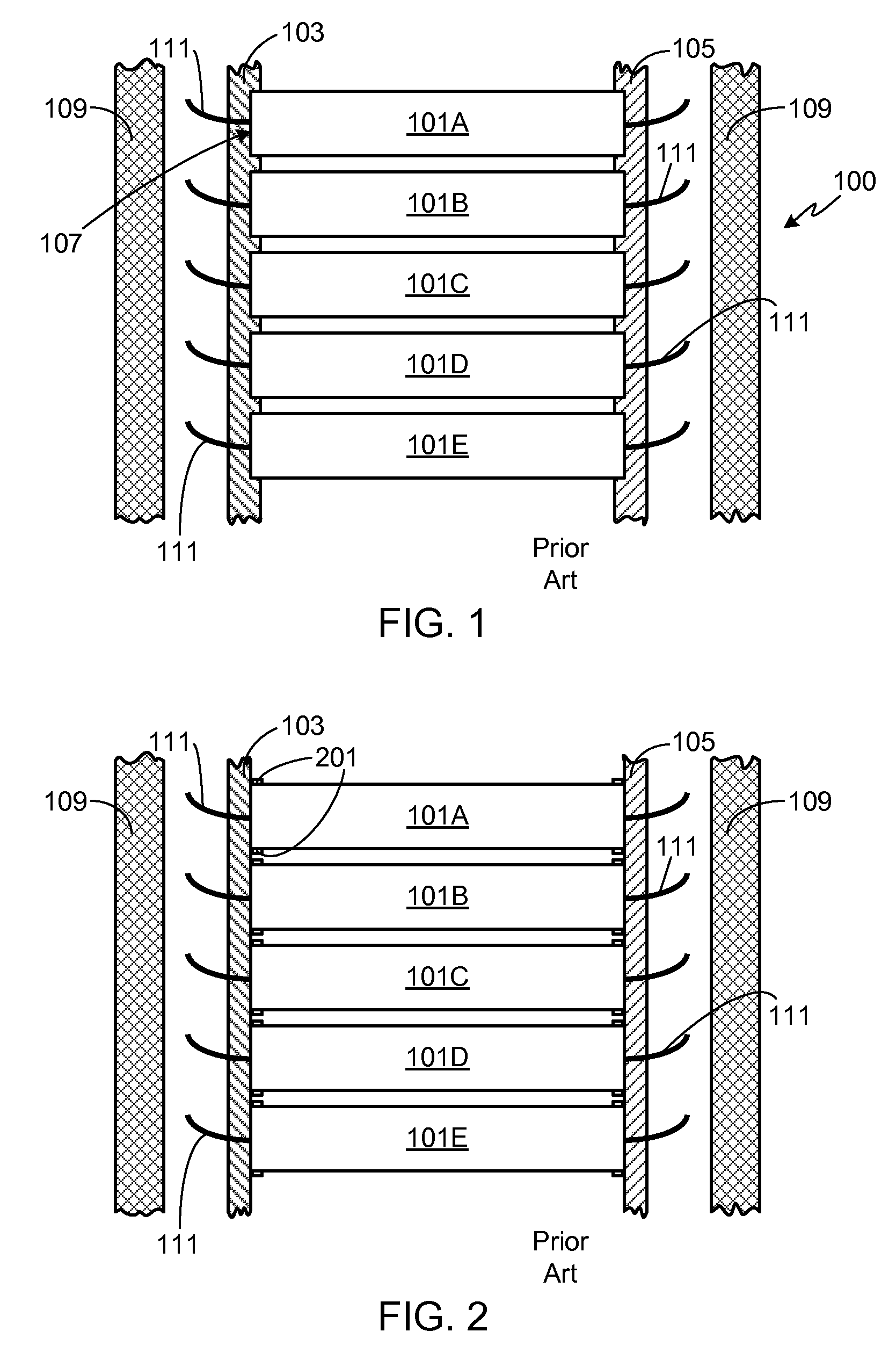
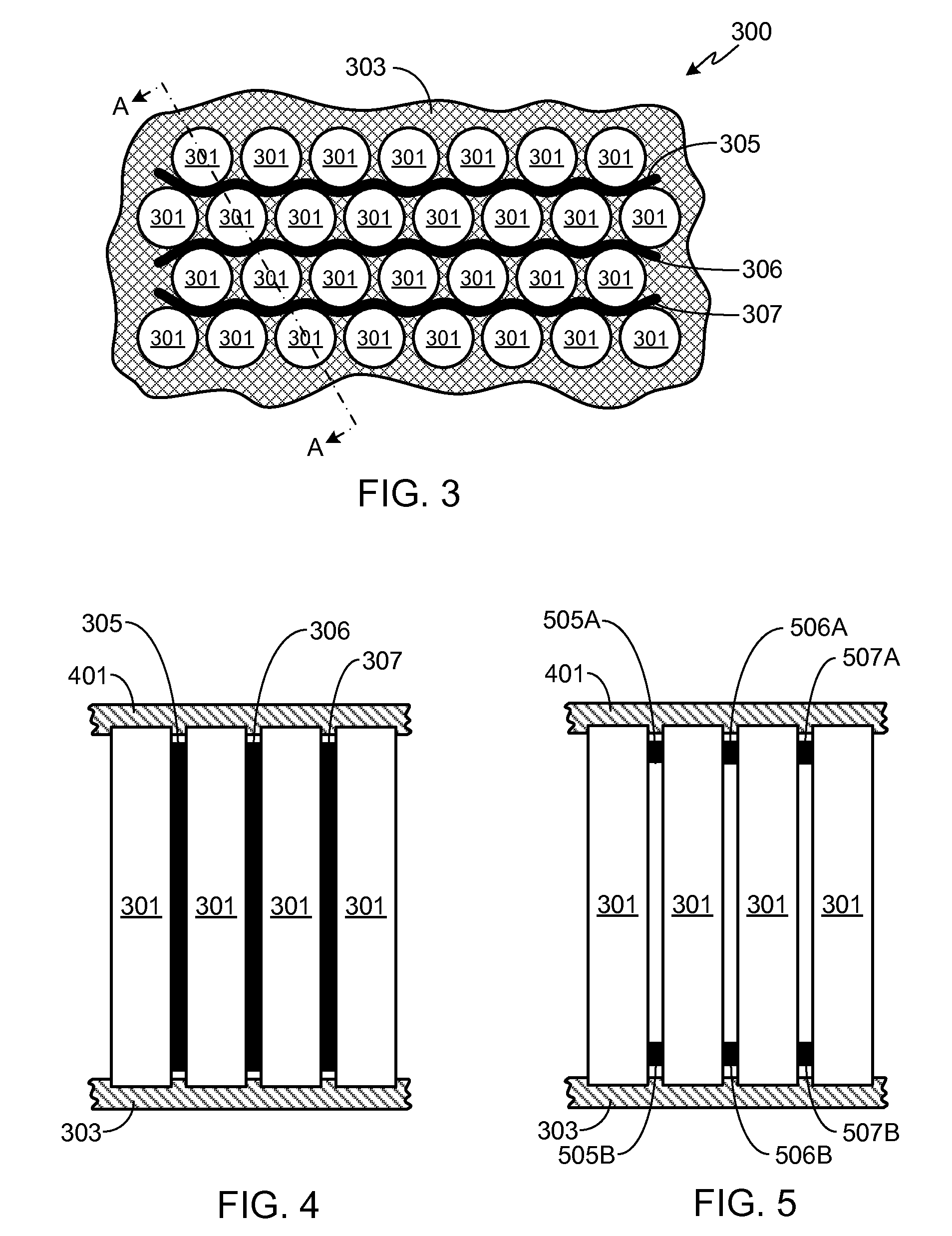
[0023]In the following text, the terms “battery”, “cell”, and “battery cell” may be used interchangeably and may refer to any of a variety of different cell chemistries and configurations including, but not limited to, lithium ion (e.g., lithium iron phosphate, lithium cobalt oxide, other lithium metal oxides, etc.), lithium ion polymer, nickel metal hydride, nickel cadmium, nickel hydrogen, nickel zinc, silver zinc, or other battery type / configuration. The term “battery pack” as used herein refers to multiple individual batteries contained within a single piece or multi-piece housing, the individual batteries electrically interconnected to achieve the desired voltage and capacity for a particular application. It should be understood that identical element symbols used on multiple figures refer to the same component, or components of equal functionality. Additionally, the accompanying figures are only meant to illustrate, not limit, the scope of the invention and should not be consi...


PUM


Abstract

A spacer assembly for use with a cell mounting bracket in a battery pack is provided. The spacer assembly, comprised of one or more spacers, maintains the positions of the batteries within the battery pack during a thermal event and after the cell mounting bracket loses structural integrity due to the increased temperature associated with the thermal event. By keeping the battery undergoing thermal runaway in its predetermined location within the battery pack, the minimum spacing between cells is maintained, thereby helping to minimize the thermal effects on adjacent cells while ensuring that the cooling system, if employed, is not compromised. As a result, the risk of thermal runaway propagation is reduced.

Description

FIELD OF THE INVENTION[0001]The present invention relates generally to batteries, and more particularly, to a means for minimizing the propagation of thermal runaway within a battery pack.BACKGROUND OF THE INVENTION[0002]Batteries can be broadly classified into primary and secondary batteries. Primary batteries, also referred to as disposable batteries, are intended to be used until depleted, after which they are simply replaced with one or more new batteries. Secondary batteries, more commonly referred to as rechargeable batteries, are capable of being repeatedly recharged and reused, therefore offering economic, environmental and ease-of-use benefits compared to a disposable battery.[0003]Although rechargeable batteries offer a number of advantages over disposable batteries, this type of battery is not without its drawbacks. In general, most of the disadvantages associated with rechargeable batteries are due to the battery chemistries employed, as these chemistries tend to be less...

Claims


Application Information

Patent Timeline
IPC IPC(8): H01M2/10H01M50/209H01M50/211H01M50/213H01M50/293
CPCH01M2/1077H01M10/504H01M2/1094H01M10/4207H01M10/653Y02E60/10H01M50/293H01M50/213H01M50/211H01M50/209H01M50/24
Inventor HERMANN, WESTON ARTHURBECK, DAVID G.
Owner TESLA INC
Features
  • Generate Ideas
  • Intellectual Property
  • Life Sciences
  • Materials
  • Tech Scout
  • Unparalleled Data Quality
  • Higher Quality Content
  • 60% Fewer Hallucinations
Learn More