Drive Unit with Cooling Circuit and Separate Heat Recovery Circuit

a heat recovery circuit and cooling circuit technology, applied in steam, mechanical equipment, machines/engines, etc., can solve the problems of only starting to work efficiently at high pressure, engine coolant and exhaust gas temperatures are not sufficient to evaporate the work medium at high pressure, and achieve high heat recovery efficiency and efficient cooling

Active Publication Date: 2010-06-10
MAN TRUCK & BUS AG
View PDF4 Cites 83 Cited by
  • Summary
  • Abstract
  • Description
  • Claims
  • Application Information

AI Technical Summary

Benefits of technology

[0006]It is an object of the present invention to improve the drive device known from DE 10 2006 010 247 A1 and its cooling system such that the combustion engine, charge air, and the recycle exhaust gas can be efficiently cooled, and a highly efficient heat recovery can be achieved by making better use of the heat source exhaust gas.
[0008]By the inventive concept of providing two parallel heat exchangers, i.e., an EGR heat exchanger and an exhaust gas heat exchanger serving to evaporate the work medium, steam can be generated immediately using one respective heat source. In addition, the work medium enters each of the two heat exchangers at a low temperature and, therefore, also achieves the desired highly efficient cooling effect for the medium from which the heat is extracted (recycled exhaust gas and exhaust gas before exiting into the atmosphere). Another advantage is that only the heat of the useful steam need be discharged in the condenser. Therefore, according to the invention, the exhaust gas heat energy available in the heat recovery circuit in the two heat exchangers, which are connected in parallel, is converted in an optimal manner for the steam energy that can then be converted by the expander into useful mechanical energy to the maximum extent. This mechanical energy can be converted by the expander, e.g., into rotational energy and supplied, to the internal combustion engine to boost output or to a generator for generating electrical energy with a correspondingly high performance yield.

Problems solved by technology

Further studies have shown that the expander only starts to work efficiently at high pressures.
However, with a serial flow through the above-mentioned heat exchangers the temperatures of the charge air, engine coolant and exhaust gas are not sufficient to evaporate the work medium at high pressures.
Therefore, large quantities of work medium must be pumped through the second cooling circuit in the known system, with the result that this amount of work medium cannot be completely vaporized even by the heat of higher-output heat sources when flowing through the latter so that a separation system for the liquid phase is mandatory.
Further, because of these factors, the returned exhaust gas cannot be cooled to the desired low temperature level when flowing through the one or more EGR heat exchangers because the work medium is already preheated when entering the one or more EGR heat exchangers.

Method used


Image

  • Drive Unit with Cooling Circuit and Separate Heat Recovery Circuit
  • Drive Unit with Cooling Circuit and Separate Heat Recovery Circuit
  • Drive Unit with Cooling Circuit and Separate Heat Recovery Circuit

Examples


Embodiment Construction

[0020]To facilitate understanding, identical or corresponding structural components or parts thereof are designated by the same reference numbers in the drawings.

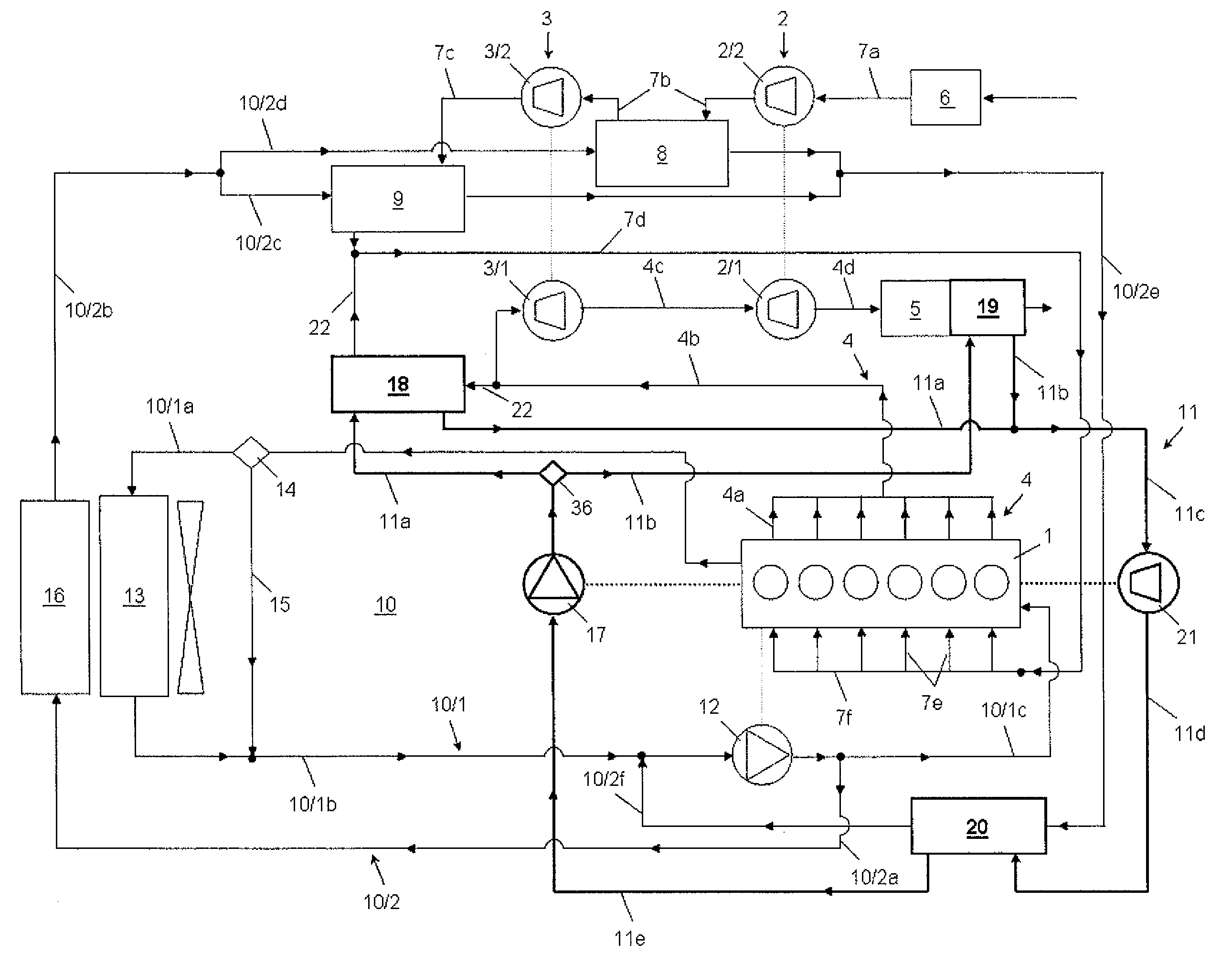
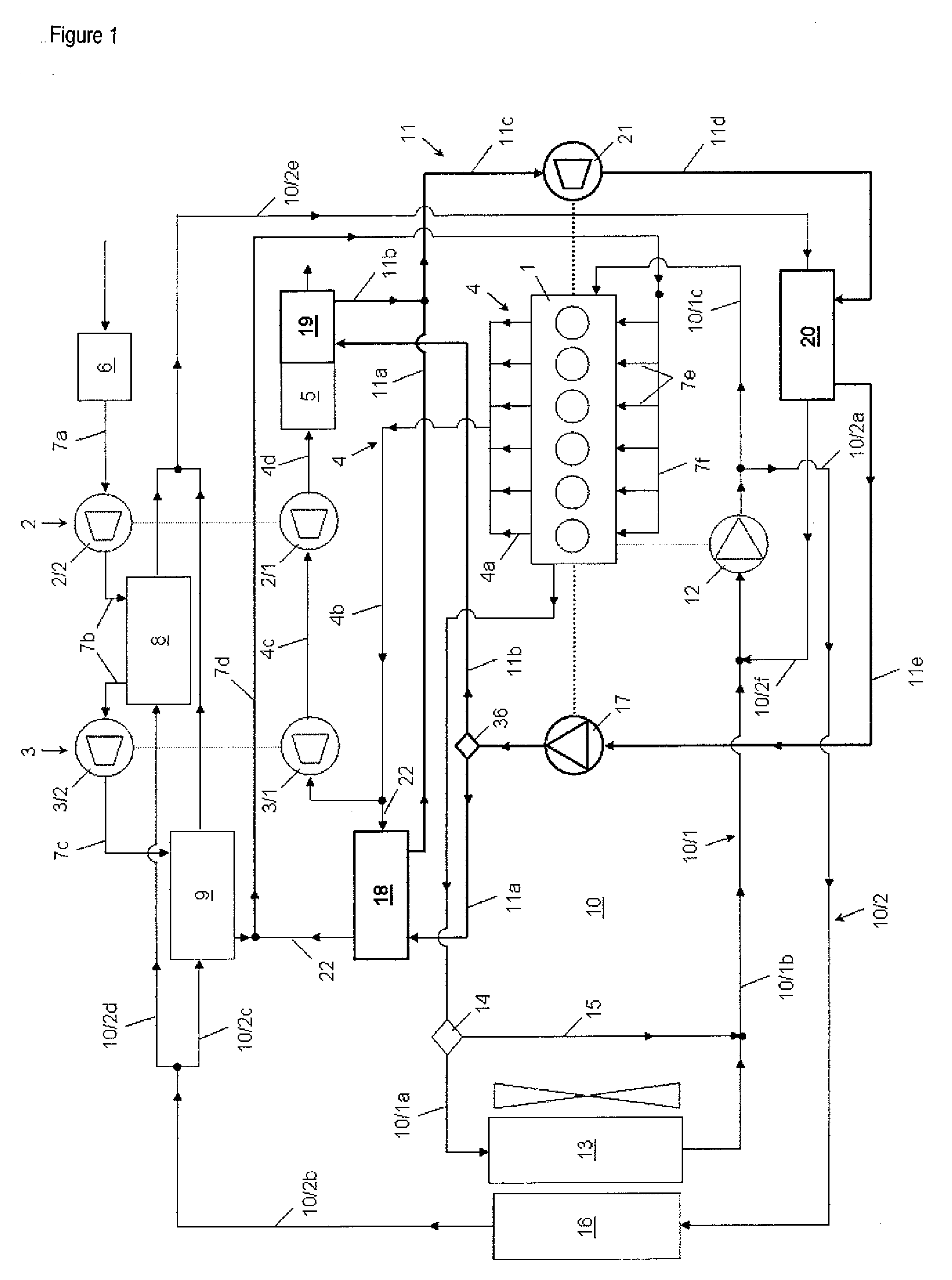
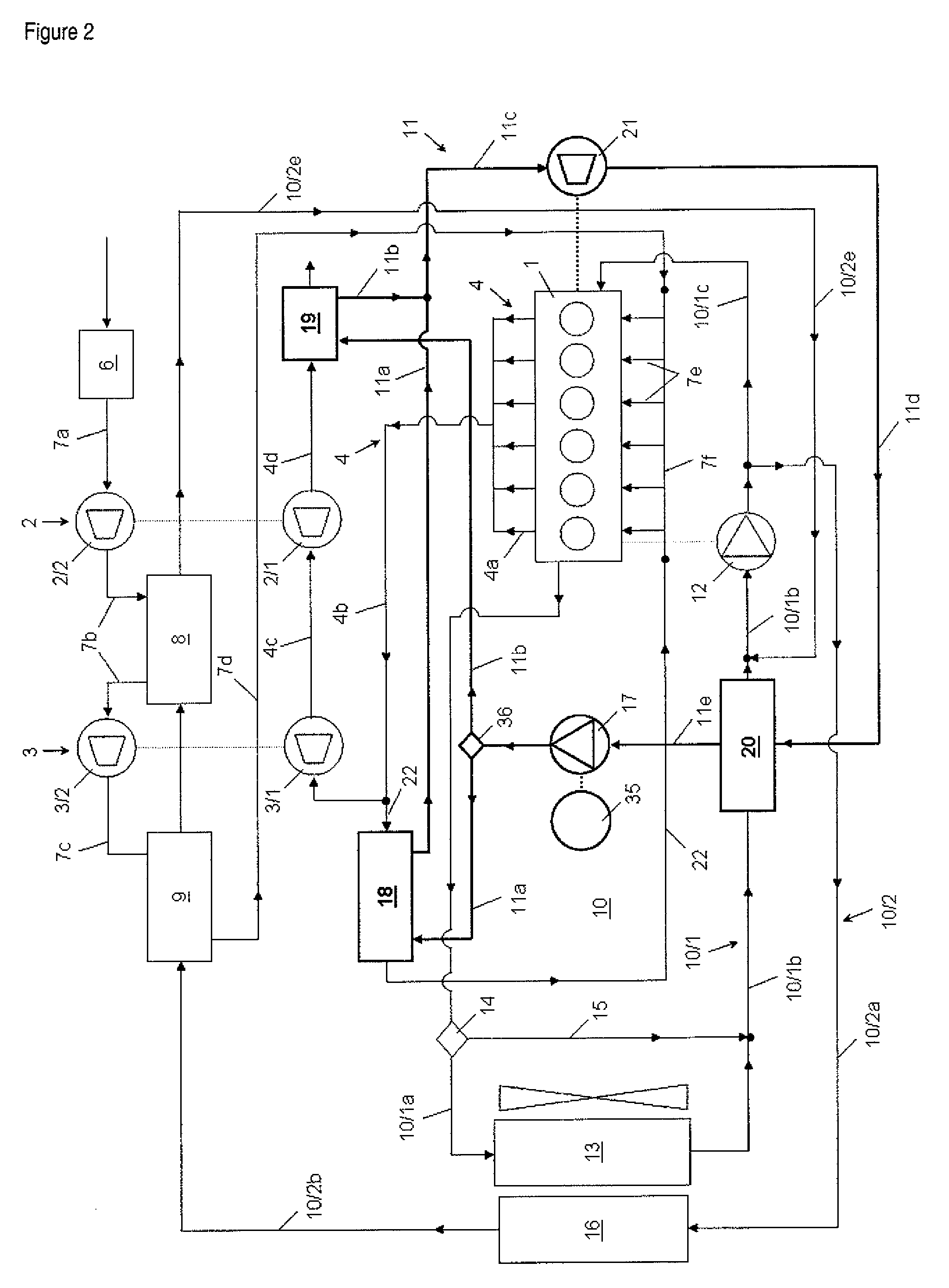
[0021]The invention is associated with a drive unit whose principal part is an internal combustion engine 1 which in turn forms the drive source for a motor vehicle, any kind of utility vehicle, rail-borne vehicle, watercraft, or in stationary installations such as cogeneration plants, emergency power units, and other known or hereafter developed installations.

[0022]The internal combustion engine 1 is charged in two stages by two exhaust gas turbochargers 2, 3. The exhaust turbocharger 2 forming the low-pressure stage comprises a low-pressure turbine 2 / 1 and a low-pressure compressor 2 / 2 driven by the low-pressure turbine 2 / 1. The exhaust turbocharger 3 forming the high-pressure stage comprises a high-pressure turbine 3 / 1 and a high-pressure compressor 3 / 2 driven by the high-pressure turbine 3 / 1.

[0023]The exhaust gas is dis...


PUM


Abstract

A cooling circuit and an independent heat recovery circuit are associated with an internal combustion engine. A coolant is circulated a pump in a first and a second cooling sub-circuit. An increase in pressure in a work medium is achieved within the heat recovery circuit by a pump. This work medium is changed from liquid aggregate state to vaporous aggregate state and back to the liquid aggregate state in heat exchangers. This work medium is divided after the pump into two parallel partial flows and is changed into vaporous state in a first parallel branch in an EGR heat exchanger through which recycle exhaust gas flows and in a second parallel branch in an exhaust gas heat exchanger through flow exhaust gas downstream of the low-pressure turbine flows. This vaporous work medium is then fed to an expander and is then conducted through a cooled condenser and, liquefied again.

Description

BACKGROUND OF THE INVENTION[0001]1. Field of the Invention[0002]The invention is directed to a drive unit, particularly in a motor vehicle, with an internal combustion engine that is charged in two stages by two exhaust turbochargers and which has a charge air supply having a low-pressure compressor, a high-pressure compressor, an intermediate charge air cooler arranged between the low-pressure compressor and the high-pressure compressor, and a main charge air cooler downstream of the high-pressure compressor. The drive unit has an exhaust gas discharge including a high-pressure turbine, a low-pressure turbine and an exhaust gas aftertreatment device downstream in the exhaust train, and a cooling installation with a cooling circuit and a heat recovery circuit, which is hydraulically decoupled from the latter.[0003]2. Description of the Related Art[0004]A drive unit is disclosed in DE 10 2006 010 247 A1. A feature of this known drive unit is that its first cooling circuit and its sec...

Claims


Application Information

Patent Timeline
Patent Type & Authority Applications(United States)
IPC IPC(8): F02M15/00F02M25/07
CPCY02E20/14F01K23/065F01P7/165F01P2060/02F02B29/0412F02B29/0443F02M25/0731F01N3/2885F01N3/2889F01N5/02F02G5/04F02B37/013F02M25/0711F02M25/0732F01N2240/02F02G2260/00Y02T10/146Y02T10/16Y02T10/166F01K17/04Y02T10/121F02M26/08F02M26/24F02M26/28Y02T10/12
Inventor RAAB, GOTTFRIEDRAUP, MARKUSKLAMMER, JOSEF
Owner MAN TRUCK & BUS AG
Why Eureka
Try Eureka