
Switching control system of circuit breaker

a technology circuit breakers, which is applied in the integration of power network operation systems, manufacturing tools, sustainable buildings, etc., can solve the problems of poor work efficiency, inconvenient remote control, slow communication speed, etc., and achieve the effect of easy acquisition and storage of synchronous switching control related data

Inactive Publication Date: 2010-06-10
KK TOSHIBA
View PDF2 Cites 21 Cited by
  • Summary
  • Abstract
  • Description
  • Claims
  • Application Information

AI Technical Summary

Benefits of technology

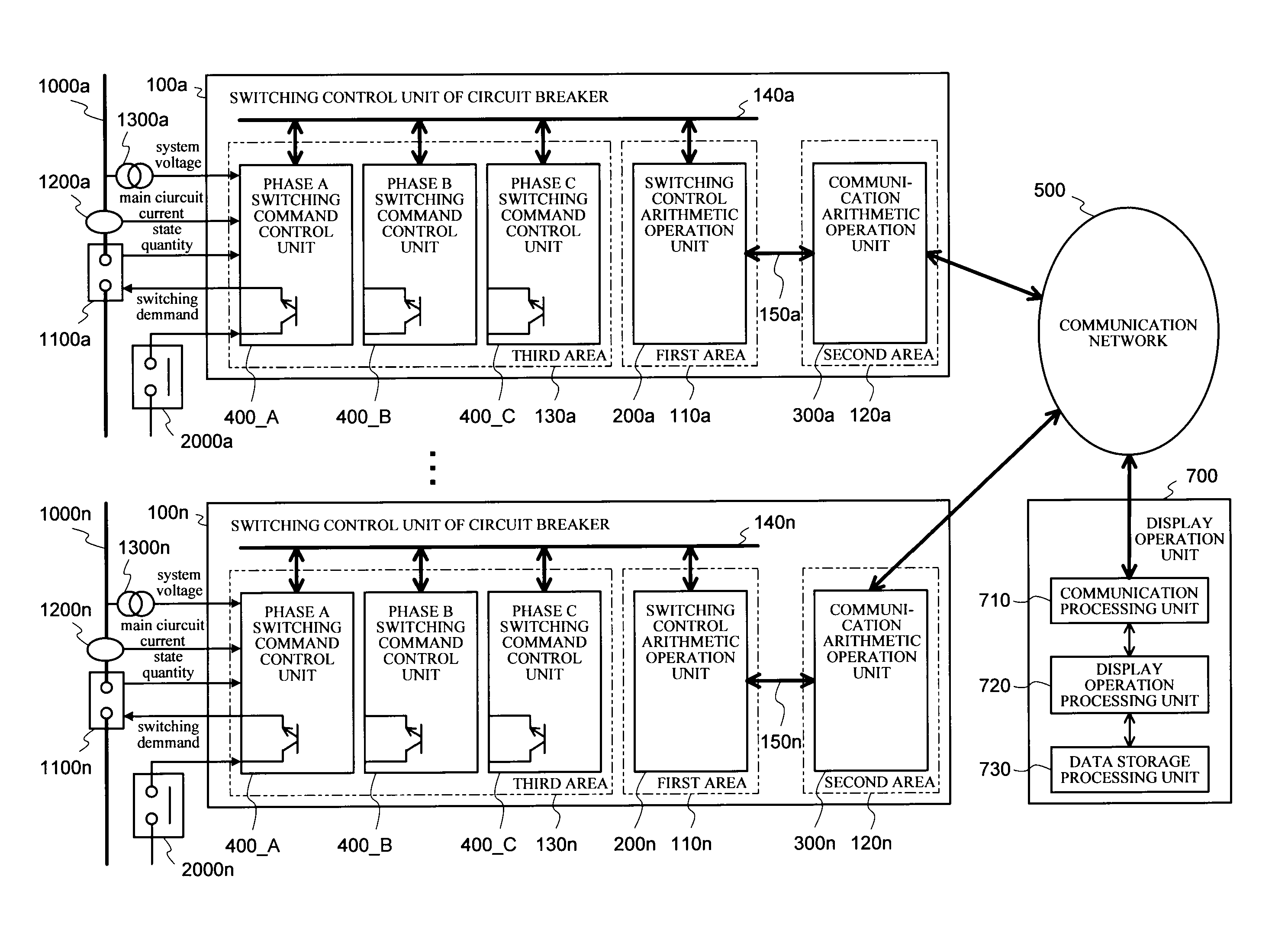
[0011]With the foregoing in view, it is an object of the present invention to provide a switching controlgear of circuit breaker which can easily connect with such an external equipment as a PC, both at the work site and remote side, without using dedicated software, and can implement efficient maintenance and data collection.
[0012]It is a second object of the present invention to provide a switching controlgear of circuit breaker which does not cause a malfunction or non-operation of a circuit breaker by a single abnormality of the switching controlgear of circuit breaker.
[0013]It is a third object of the present invention to provide an economical and high functioning switching controlgear of circuit breaker which can contribute to energy saving during circuit breaker maintenance, and an easy and quick handling of accidents, by integrating a circuit breaker monitoring function (gas pressure, contact erosion quantity calculation, circuit breaker operation time), can improve operability of the circuit breaker and system, and thereby improve cost of the entire facility.
[0016]According to the present invention, a switching control unit of circuit breaker, which can easily acquire and store synchronous switching control related data from a switching control unit of circuit breaker in a remote site via a communication network by having display / operation / data processing software, which is installed and operates in a display operation unit constructed by a general purpose computer, function as a human interface (HMI), can be provided.

Problems solved by technology

Therefore the PC, in which the dedicated software is not installed, cannot be connected to the switching controlgear of circuit breaker, which is inconvenient, especially in terms of storing and managing various acquired data.
Therefore in the case of the switching controlgear of circuit breaker shown in Non-patent Document 1, connection with a PC is normally a local connection at the work site, which is not convenient for remote control.
If remote control is required, [the switching controlgear of circuit breaker] must be connected using a modem via a telephone line, for example, instead of an RS-232C cable, which is not only inconvenient but also has a slow communication speed and poor work efficiency.
Also only one switching controlgear of circuit breaker can be connected to one PC at a time, which means that a switching operation is required to perform maintenance and various data collection for the switching controlgear of circuit breakers installed in a plurality of circuits, which has poor work efficiency.

Method used


Image

  • Switching control system of circuit breaker
  • Switching control system of circuit breaker
  • Switching control system of circuit breaker

Examples


embodiment 1

(Variant Form of Embodiment 1)

[0146]The above mentioned switching control system of circuit breaker according to Embodiment 1 can be constructed as shown in the following variant form.

[0147]In a plurality of electric stations, the switching control unit of circuit breaker 100 and the display operation unit 700 are connected to a local network of each electric station. This local network of each electric station is interconnected to a wide area network via a router and gateway. For the wide area network, a circuit switching network, such as a telephone line, is used.

[0148]In this variant form as well, functions and effects similar to the switching control system of circuit breaker according to Embodiment 1 can be implemented. In addition, by constructing the switching control system of circuit breaker connected to the wide area network like this, the switching control units of circuit breaker 100 installed in a plurality of different electric stations can be easily remote controlled....

embodiment 2

[0151]Embodiment 2 of the present invention will now be described with reference to the switching control system of circuit breaker diagram in FIG. 4.

(Configuration)

[0152]In FIGS. 4, 100a to 100n are the switching control units of circuit breaker, 550 is a wireless communication network, and 700 is a display operation unit, which are the major composing elements of the switching control system of circuit breaker of Embodiment 2.

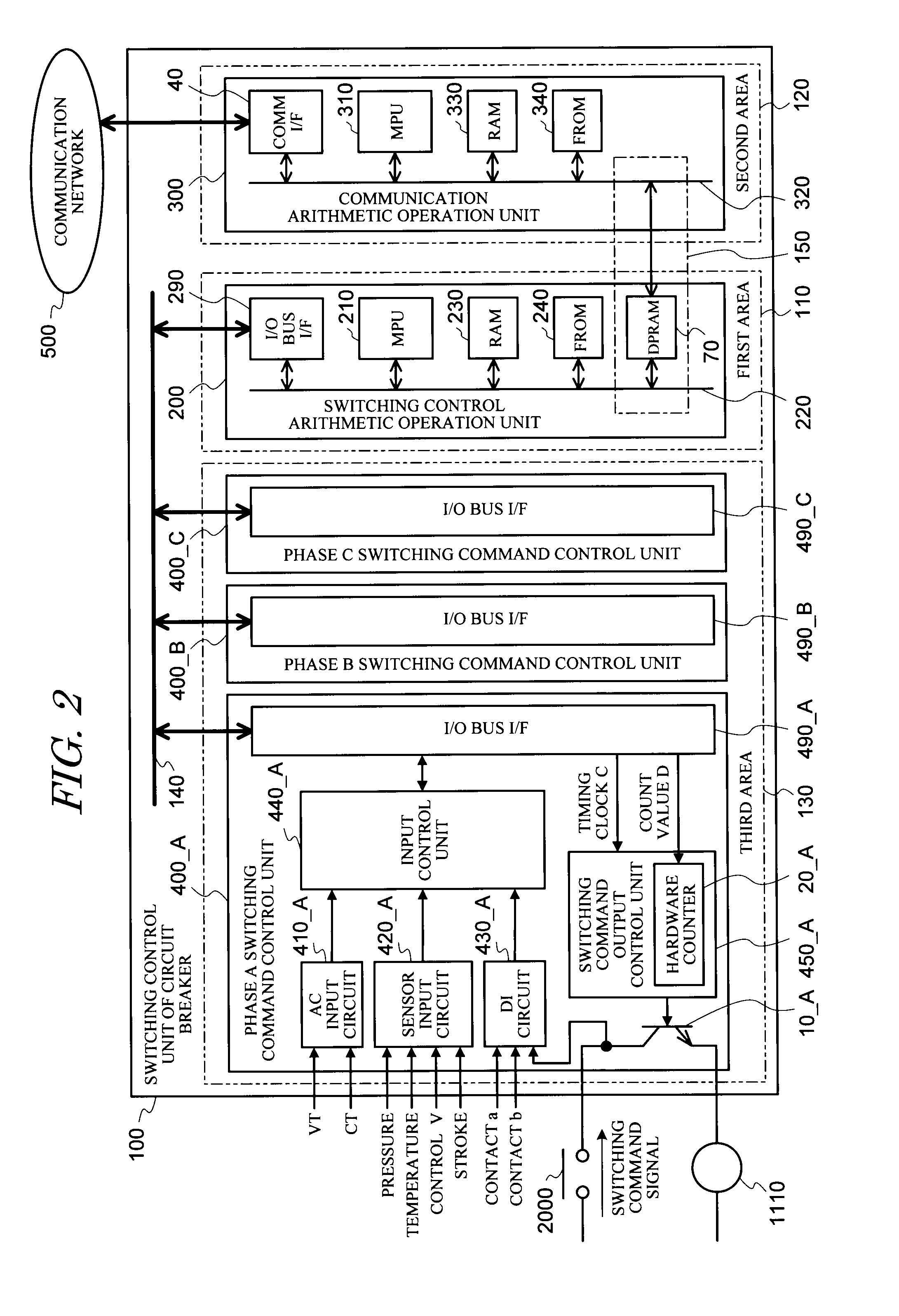
[0153]The communication arithmetic operation units 300a to 300n of the switching control units of circuit breaker 100a to 100n in FIG. 4 enclose wireless communication means 50a to 50n respectively. The wireless communication means 50 is the communication interface 40 of the above mentioned Embodiment 1 shown in FIG. 2, of which all or a part is replaced. Needless to say, the wireless communication means 50 and the cable communication interface 40 may be used together. The other detailed configuration of the switching control unit of circuit breaker 100 is th...

embodiment 3

[0164]Embodiment 3 of the present invention will now be described with reference to the diagram depicting the switching control system of circuit breaker in FIG. 5.

(Configuration)

[0165]In FIGS. 5, 100a to 100n are the switching control units of circuit breaker, 500 is a communication network, and 700 is a display operation unit. The configuration of these composing elements is the same as the switching control system of circuit breaker of Embodiment 1, so detailed description thereof is omitted.

[0166]Differences of the switching control system of circuit breaker of Embodiment 3 from the switching control system of circuit breaker of Embodiment 1 are as follows.

(1) Web Server 800 Installed in the Communication Arithmetic Operation Unit of the Switching Control Unit of Circuit Breaker

[0167]The web server 800 is software having an information transmission function by WWW (World Wide Web) which runs on the communication operation MPU 310 (see FIG. 2) of the communication arithmetic oper...


PUM

PropertyMeasurementUnit
lengthaaaaaaaaaa
voltageaaaaaaaaaa
currentaaaaaaaaaa

Abstract

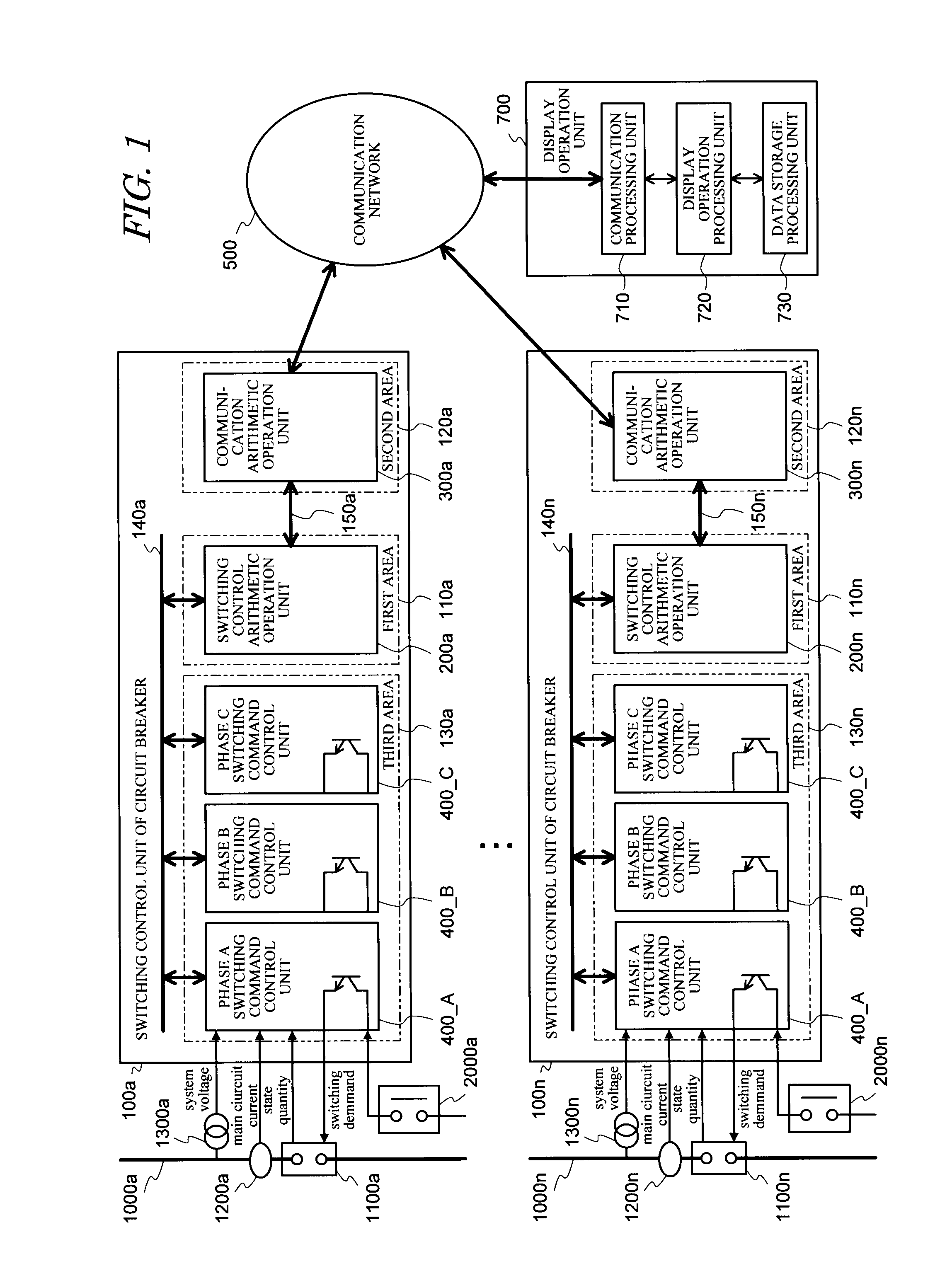
A switching control system of circuit breaker is provided, which can easily connect with such an external equipment as a PC, both at the work site and remote side, without using dedicated software, and can implement efficient maintenance and data collection. The system comprises: one or more switching control units of circuit breaker 100 each of which inputs electrical quantity of power system voltage and main circuit current, state quantity of a circuit breaker, and an opening command signal or closing command signal of the circuit breaker, and performs control to cause the circuit breaker to open or close at a desired phase of the power system voltage or main circuit current; and a display operation unit 700, which is connected with the switching control unit of circuit breaker via a communication network 500 and performs display operation to operate and monitor the operation and state of the switching control unit of circuit breaker. The switching control unit of circuit breaker comprises: a first area 110 serving as switching control arithmetic operation means for causing the circuit breaker to open or close at a desired phase of the power system voltage or main circuit current; and a second area 120 serving as communication arithmetic operation means for transmitting / receiving information from the display operation unit or transmitting information of the first area, via the communication network.

Description

TECHNICAL FIELD[0001]The present invention relates to a switching control system of circuit breaker, and more particularly to a switching control system of circuit breaker which prevents transient phenomena that impact electric power systems and electric power equipment by controlling the opening or closing timing of the circuit breaker.BACKGROUND ART[0002]A method for suppressing the generation of transient phenomena, which impact electric power systems and electric power equipment, by controlling the opening or closing timing of a circuit breaker for power, has been proposed (e.g. see Non-patent Document 1).[0003]A specific invention to implement this method for suppressing the generation of transient phenomena, which has already been proposed, is a switching controlgear of circuit breaker which switches a circuit breaker contact at a timing between a current zero point and a peak value of the circuit breaker current when current is interrupted, and controls the closing timing of ...

Claims


Application Information

Patent Timeline
Patent Type & Authority Applications(United States)
IPC IPC(8): H01H7/00
CPCH01H9/563H01H2300/03H02J13/0086Y04S20/227Y04S20/14Y02B70/3241Y02B90/224H02J13/00017H02J13/00028H02J13/00036H02J13/0004Y02B90/20Y04S10/18Y04S40/124Y02E60/00Y02B70/30Y04S20/20
Inventor SAITO, MINORUMAEHARA, HIROYUKEMARUYAMA, SHIRO
Owner KK TOSHIBA
Learn More