Orthogonal linear transmit receive array radar

a transmit-receive array and radar technology, applied in the field of sensing systems, can solve the problems of high acoustic vibration and shock levels imposed on helicopters from environmental and operational conditions, and the cost of module integration into phased arrays, and achieve the effect of high resolution and high resolution

Active Publication Date: 2010-06-10
FIRST RF CORP
View PDF32 Cites 184 Cited by
  • Summary
  • Abstract
  • Description
  • Claims
  • Application Information

AI Technical Summary

Benefits of technology

[0028]In the radar system of the present invention, the orthogonal antenna system may provide high resolution imaging at a microwave frequency or at millimeter wave frequency.
[0029]In an alternate embodiment, the at least one transmit aperture may be switched to operate in a receive mode and the at least one receive aperture is simultaneously switched to operate in a transmit mode. In this alternate embodiment, the at least one transmit aperture and the at least one receive aperture may be provided in a horn, pill box, planar, dielectric lens, dielectric rod, Cassegrain, parabolic, elliptical, circular dish or linear shape. The orthogonal antenna system may comprise at least one transmit aperture that rotates on a first one-axis gimbal and at least one receive aperture that rotates on a second one-axis gimbal in a plane orthogonal to the at least one transmit aperture. The alternate embodiment orthogonal antenna system may also comprise at least one transmit aperture that further comprises at least one linear phased array, and at least one receive aperture that further comprises at least one linear phased array. The at least one linear phased array transmit aperture and the at least one linear phased array receive aperture each may further comprise a plurality of antenna elements disposed on an array face and connected by a combining network, wherein each of the antenna elements further comprises a radiator and a phase shifter. The orthogonal antenna system, having a linear length of between 1.0 and 1.5 times that of a fully populated square 2D scan array, may generate a composite narrow beam cross-product that is substantially the same resolution as the fully populated square 2D scan array. The at least one linear phased array transmit aperture and the at least one linear phased array receive aperture may be scanned via mechanical scanning, electronic beam switching, electronically scanned phased array or digital beamforming. The alternate embodiment orthogonal antenna system may provide high resolution imaging at a microwave frequency and at a millimeter wave frequency.

Problems solved by technology

The main cost drivers for phased arrays typically are the module cost and the cost of integration of the modules into the phased arrays.
In many radars, performance may be limited by the beamwidth (clutter) of the system and the necessity to generate and track multiple targets.
As is well known, the acoustic, vibration and shock levels imposed on a helicopter from environmental and operational conditions are much more severe than those imposed on other air platforms.
Known systems have degraded and / or limited range in adverse weather and brownout sand and dust storm conditions, however, that have limited the flight safety in desert and high precipitation environments.
These limitations can also leave a helicopter open to other risks and vulnerabilities, including trap wires strung between buildings and trees when common ingress and egress paths of a helicopter are known.
Urban / suburban landing and takeoffs can also become dangerous if nearby mobile land vehicles are in close proximity to a makeshift helicopter landing site.
For example, where these mobile land vehicles have limited visibility to approaching aircraft in a tactical brownout environment, the vehicles may not be able to move out of the way of the landing helicopter, and it may be difficult for the incoming helicopter to detect the mobile vehicles.
Other ground-based human activities in urban operations can also interfere with a helicopter's safe landing.
The logistics, maintenance, and support of the mechanically scanned antenna systems often become the most important cost driver and the limiting factor of the system.
The limitation then becomes the cost of the MMW phased array.
The end result produces a considerable real estate competition / shortage and / or platform antenna(s) integration issue.
These issues may include interference and blockage from multiple single function RF apertures that often will degrade the radars stand-alone and modeled performance.
Thus, in addition to weight and cost considerations, a major challenge is the need to find the optimum way to integrate the radar antenna's functionality onto the helicopter platform while allowing for multiple simultaneous RF functions to exist, all without degradation to either the radar's stand-alone performance or that of the other RF systems.

Method used


Image

  • Orthogonal linear transmit receive array radar
  • Orthogonal linear transmit receive array radar
  • Orthogonal linear transmit receive array radar

Examples


Embodiment Construction

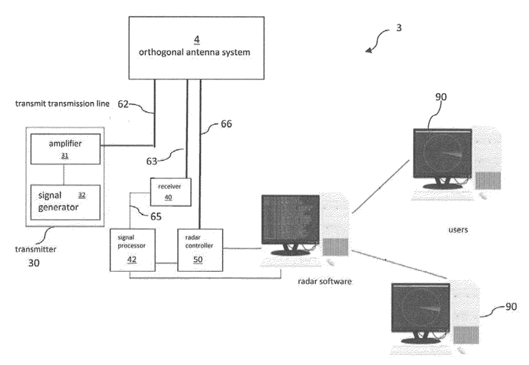
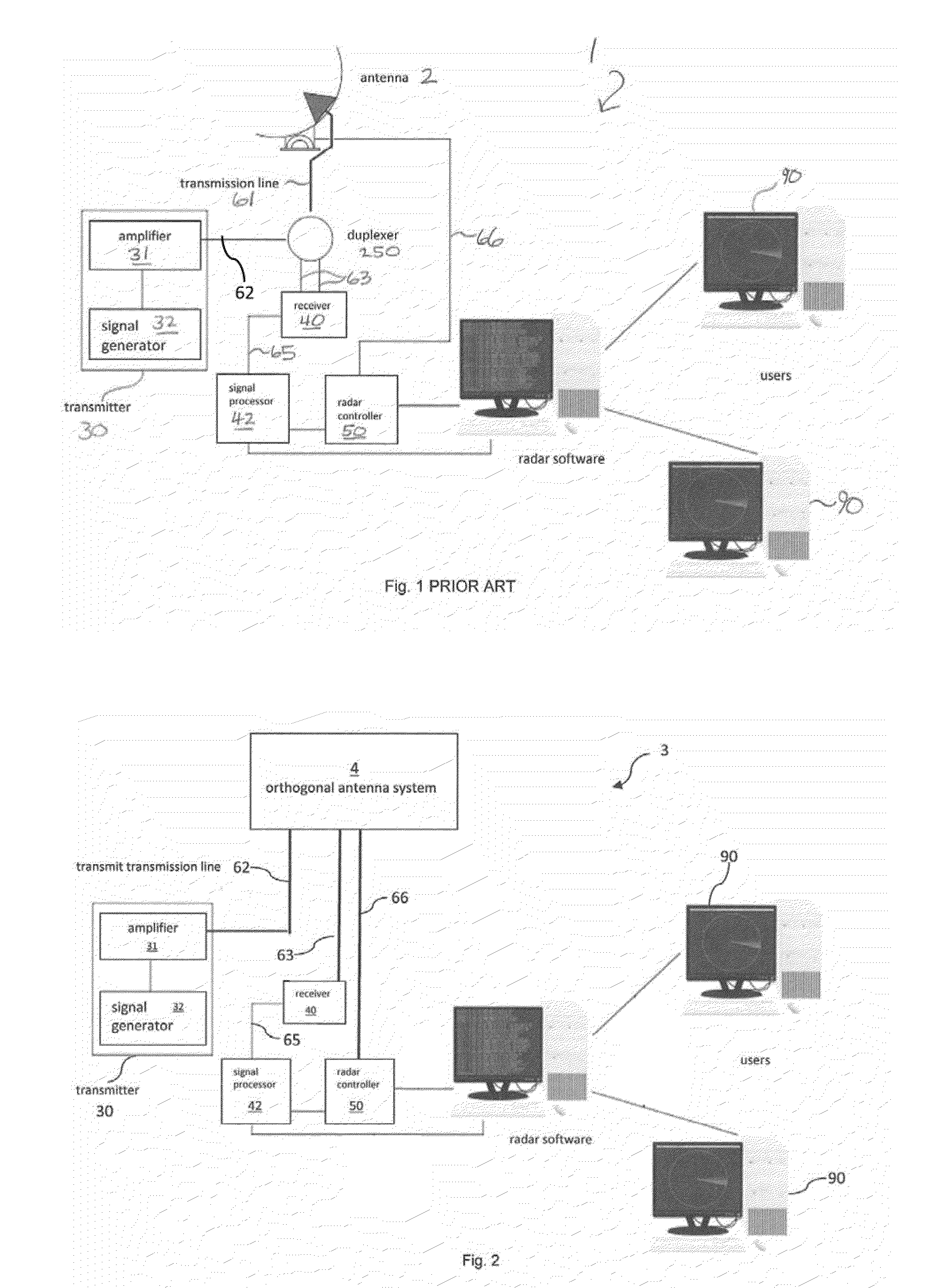
[0068]Referring now to FIG. 1, a schematic representation of a typical prior art radar system 1 is shown. Radar system 1 comprises antenna 2 for transmitting and receiving RF signals. Antenna 2 is connected by transmit / receive transmission line 61 to duplexer 250. Duplexer 250 is in turn connected to transmitter 30, via transmit transmission line 62. Transmitter 30 further comprises signal generator 32 and amplifier 31. Signal generator 32 produces a transmitted signal, which is amplified by amplifier 31 and then is fed to antenna 2. Duplexer 250 is also connected to receiver 40 via receive transmission line 63. Receiver 40 is in turn connected to signal processor 42, which is connected to radar controller 50. Antenna 2 receives a received signal reflected from a given object or target, and then the received signal is fed to duplexer 250 via transmission line 61, to receiver 40 via receive transmission line 63 and to radar controller 50 via controller transmission line 66. Finally, ...


PUM


Abstract

A radar system having orthogonal antenna apertures is disclosed. The invention further relates to an antenna system wherein the orthogonal apertures comprise at least one transmit aperture and at least one receive aperture. The cross-product of the transmit and receive apertures provides a narrow spot beam and resulting high resolution image. An embodiment of the invention discloses orthogonal linear arrays, comprising at least one electronically scanned transmit linear array and at least one electronically scanned receive linear array. The design of this orthogonal linear array system produces comparable performance, clutter and sidelobe structure at a fraction of the cost of conventional 2D filled array antenna systems.

Description

CROSS REFERENCE TO RELATED APPLICATIONS[0001]This application is related to and claims the benefit of prior-filed United States Provisional Application for Patent Ser. No. 61 / 110,518 filed on 31 Oct. 2008, entitled “ORTHOGONAL LINEAR TRANSMIT RECEIVE ARRAY RADAR,” which is incorporated herein by reference.FIELD OF THE INVENTION[0002]The present invention relates to a sensing system having an antenna system with orthogonal apertures, and more particularly, to an antenna system wherein the orthogonal apertures comprise at least one transmit aperture and at least one receive aperture. The cross-product of the transmit and receive apertures provides a narrow spot beam and therefore, a high resolution image that is desirable for many defense and commercial applications. The present invention further discloses an embodiment having orthogonal linear arrays, comprising at least one electronically scanned transmit linear array and at least one electronically scanned receive linear array. The...

Claims


Application Information

Patent Timeline
Patent Type & Authority Applications(United States)
IPC IPC(8): H01Q3/00
CPCH01Q21/24H01Q21/08
Inventor LALEZARI, FARZIN
Owner FIRST RF CORP
Why Eureka
Try Eureka