Antenna system

a technology of antennas and antennas, applied in the field of antenna systems, can solve the problems of reducing emc properties with respect to interfering influences etc., and achieve the effects of improving emc properties, reducing am performance, and improving high-frequency performan

Inactive Publication Date: 2010-06-10
BLAUPUNKT ANTENNA SYST
View PDF7 Cites 10 Cited by
  • Summary
  • Abstract
  • Description
  • Claims
  • Application Information

AI Technical Summary

Benefits of technology

[0003]With the measures as described herein, i.e., at least one switchable terminating impedance which is coupled to the at least one conductive surface with a high resistance and at least one tap point for antenna signals on the conductive surface, in particular at a high-resistance point in its outer border, it is possible to achieve improved EMC properties and an improved high-frequency performance. European Published Patent Application No. 1 076 375 also describes the need for wide conducting structures due to the low-resistance coupling conductors. One disadvantage of these wide conducting structures is the space required and the resulting proximity to the vehicle body and other conductors, e.g., the lead for the heating power, so that strong coupling is established. This reduces EMC properties with respect to interfering influences and also in particular reduces AM performance. The high-resistance coupling according to example embodiments of the present invention having at least one switchable terminating impedance and the preferred connection of the tap point for antenna signals on the conductive surface at a high-resistance point in its outer border allow the use of high-resistance lines without any special measures for adjusting the characteristic wave impedance and the resulting signal interference and losses. High-resistance lines may be implemented with narrow conduction widths, which greatly reduces the space required. The high-resistance coupling and design of the supply lines and the resulting reduction in space required allow more degrees of freedom in the design of the black print associated with this in or on the vehicle window. In contrast with European Published Patent Application No. 1 076 376, where certain minimum lengths are obligatory for the low-resistance coupling conductors, such lengths are not necessary with the conductor structures of the antenna system according to example embodiments of the present invention to achieve a clear definition of the diversity effect. In this way the antenna system may be used to advantage for smaller vehicle windows. In addition, the high-resistance supply lines between the tap point for antenna signals and the analyzer unit, e.g., antenna amplifiers of a receiving unit, as well as between the high-frequency-conductive surface and the at least one terminating impedance, may also be used with to influence the directional characteristic and thus for the reception level of the antenna, which allows a targeted design of the diversity function of the antenna system.
[0004]The conductor structure of the heating conductor field of the rear window in particular may be used as an high-frequency-conductive surface or it may be implemented as a transparent conductive coating in or on the vehicle window into which the high-resistance supply lines may be integrated. For high-resistance coupling of the tap point to the high-frequency-conductive surface, a heating conductor may be used on the outer edge of the heating field, which has a higher resistance anyway than a collective conductor connecting the heating conductors. The adjustment of the switchable terminating impedance(s) may be improved via additional conductors, in particular perpendicular to the heating conductors, normally situated in parallel, and thus the diversity effect may be potentiated. Multiple switchable terminating impedances may also be provided as well as additional tap points for antenna signals. The different antenna signals may be fed to a common analysis by a diversity analyzer unit.

Problems solved by technology

One disadvantage of these wide conducting structures is the space required and the resulting proximity to the vehicle body and other conductors, e.g., the lead for the heating power, so that strong coupling is established.
This reduces EMC properties with respect to interfering influences and also in particular reduces AM performance.

Method used


Image

  • Antenna system
  • Antenna system
  • Antenna system

Examples


Embodiment Construction

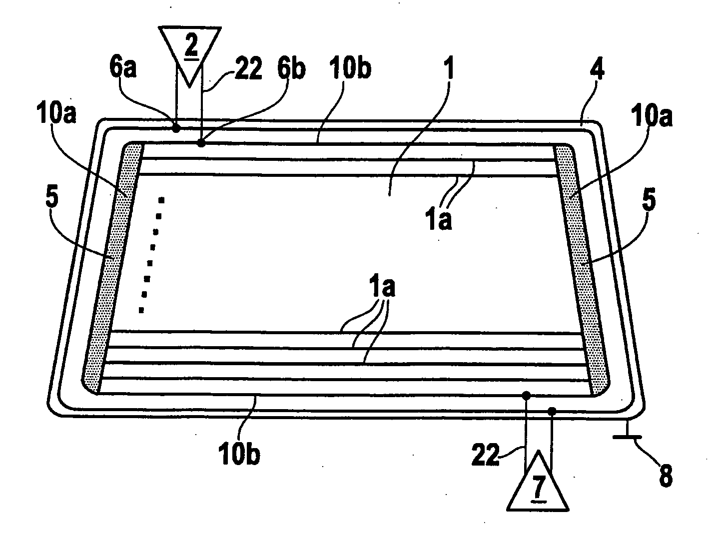
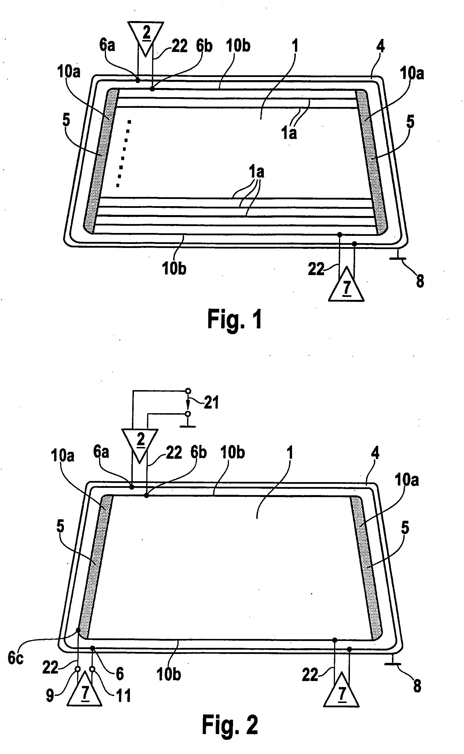
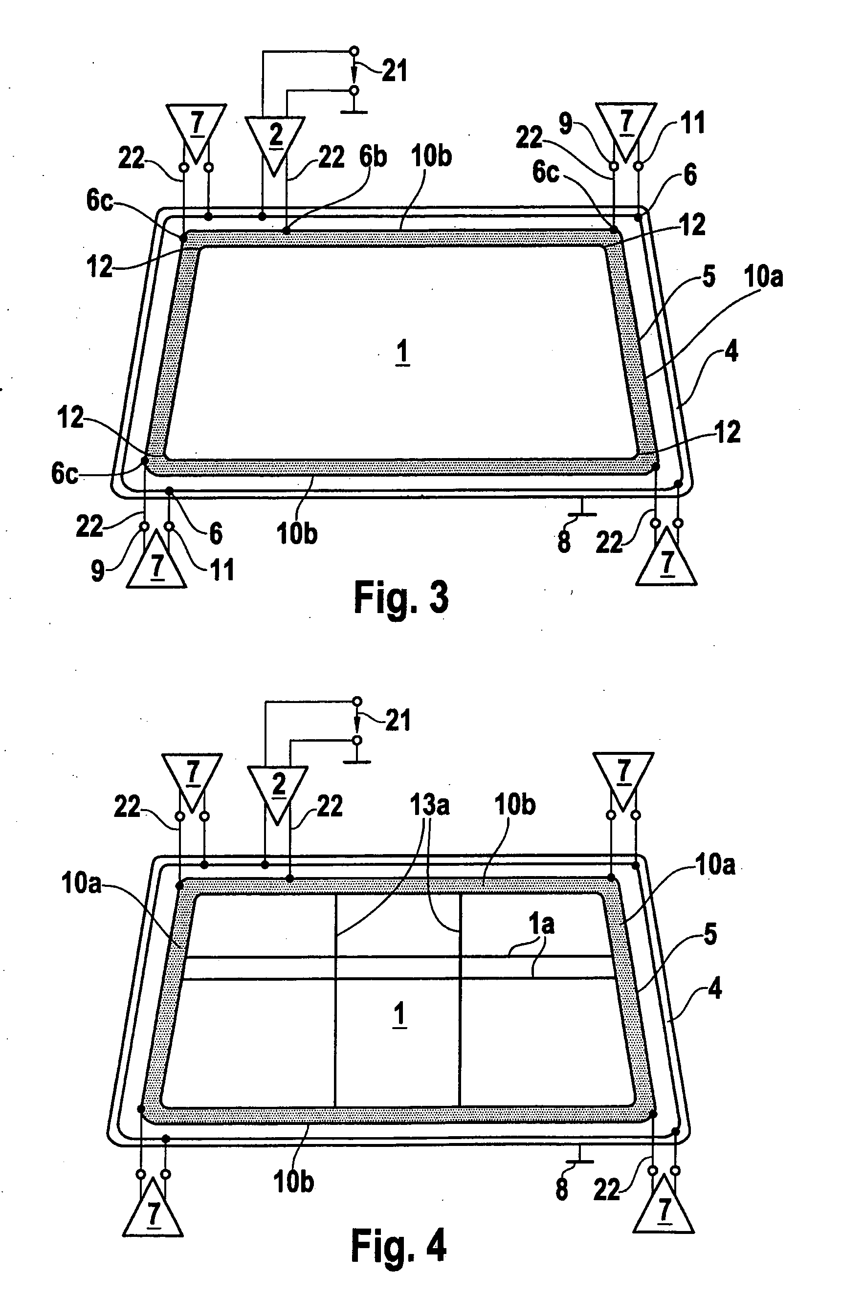
[0022]FIG. 1 shows an antenna system according to an example embodiment of the present invention for diversity operation in the VHF range in a motor vehicle in particular. The antenna system has a cohesive high-frequency-conductive surface 1, which has horizontal and / or perpendicular conductors of a heating field in or on a vehicle window, in particular the rear window or a conductive coating, e.g., a vaporized metal transparent vehicle window or sandwich structure. The edges, i.e., the outer border of high-frequency-conductive surface 1, are insulated from a grounding surface surrounding them, e.g., vehicle body 4. In the exemplary embodiment shown in FIG. 4, high-frequency-conductive surface 1 is designed as a rectangle. It may also be trapezoidal or structured in some other way in or on the vehicle window.

[0023]High-resistance supply lines 22 (the term “high resistance” as used hereinafter indicates a value of more than 10 ohm, e.g., 50 ohm or 75 ohm in the case of characteristic...


PUM


Abstract

In an antenna array, in particular for diversity operation, a cohesive radiofrequency-conductive area (1) is provided, to which switchable impedances (7) are coupled in highly resistive fashion. In order to output the antenna signals, at least one tap point (6b) is provided in particular at a highly resistive point at the outer edge of the conductive area (1).

Description

FIELD OF THE INVENTION[0001]The present invention is directed to an antenna system for diversity operation in a motor vehicle in particular, having at least one cohesive high-frequency-conductive surface, which is insulated with respect to a surrounding grounding surface, e.g., the vehicle body.BACKGROUND INFORMATION[0002]European Published Patent Application No. 1 076 375 describes such an antenna system in which boundary conductors of a predetermined minimum length are designed as low-resistance coupling conductors which are provided between a switchable terminating impedance and a low-resistance antenna signal tap point.SUMMARY[0003]With the measures as described herein, i.e., at least one switchable terminating impedance which is coupled to the at least one conductive surface with a high resistance and at least one tap point for antenna signals on the conductive surface, in particular at a high-resistance point in its outer border, it is possible to achieve improved EMC properti...

Claims


Application Information

Patent Timeline
Patent Type & Authority Applications(United States)
IPC IPC(8): H01Q1/32G01R29/08
CPCH01Q3/247H01Q1/1278
Inventor THOLE, MICHAELJANNSEN, BERTMALZAHN, THOMAS
Owner BLAUPUNKT ANTENNA SYST
Why Eureka
Try Eureka