Objective optical system

Active Publication Date: 2010-06-10
OLYMPUS CORP
View PDF3 Cites 23 Cited by
  • Summary
  • Abstract
  • Description
  • Claims
  • Application Information

AI Technical Summary

Benefits of technology

[0022]Having been made with such problems with the prior art in mind, the present invention has for its one object the provision of a high-performance imaging optical system that achieves a magnification high enough to enable microscopic viewing under an endoscope and is bet

Problems solved by technology

With the optical systems set forth in Patent Publications 2 to 4 or 7 of the above prior arts, magnifications at the time of enlarged-scale closest range viewing are not high enough for microscopic viewing.
Patent Publication 1 comes up with an enlarged-scale, high-magnification endoscope object lens; however, it has some practical problems, because the field of view upon normal viewing remains narrow, there is the need of implementing in vivo screening to find lesions, much difficulty is encountered in getting on with the affected site, and so on.
This endoscope objective lens is also less than satisfactory in terms of resolution of objects upon enlarged-scale viewing because its optical performance is not that good.
For this reason, there is parallax occurring upon switching endoscopic viewing over to microscopic viewing, and so much difficulty is experienced in identifying the range of where to view.
Further, it is difficult to fi

Method used


Image

  • Objective optical system
  • Objective optical system
  • Objective optical system

Examples


example 1

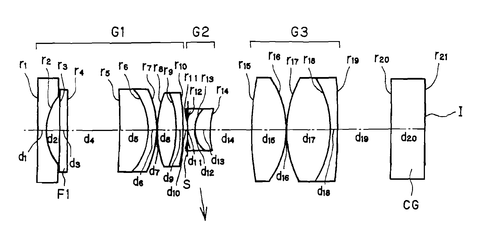
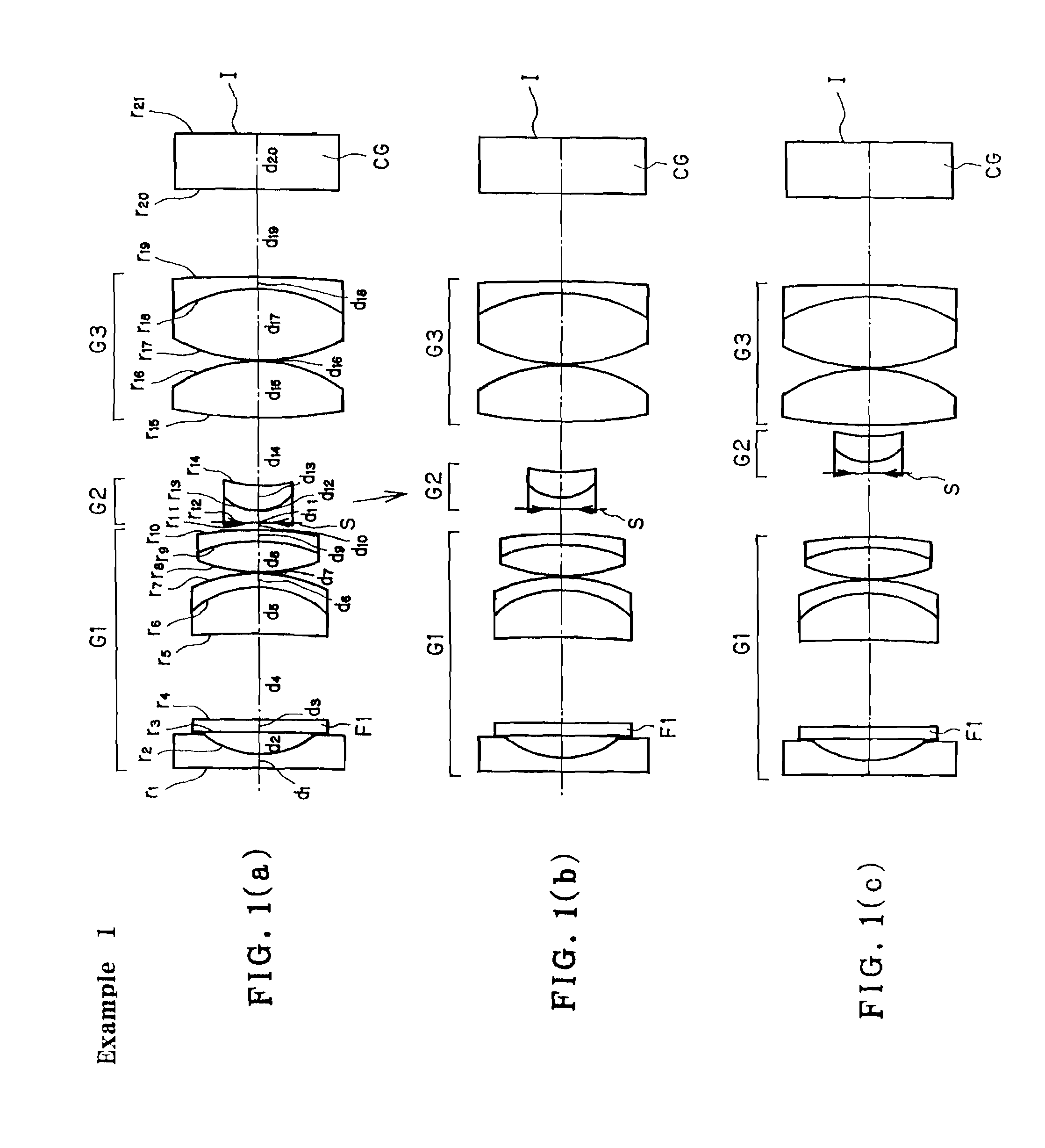
[0091]FIG. 1 is illustrative in section through the optical axis of the construction of the endoscope objective optical system according to Example 1. Numerical data on the example here will be set out in Table 1, given later, and the values of variation parameters in three viewing states: (a) normal viewing, (b) transient and (c) closest-range viewing are tabulated in Table 2, given later. In these numerical data, “No”, “r”, “d”, “ne”, and “vd” is indicative of a surface number of an optical surface as counted from the object side, a radius of curvature, a surface-to-surface or air space, an e-line refractive index, and an Abbe constant, respectively. The radius of curvature and the surface-to-surface space are given in mm. Throughout the drawings, the optical surfaces with Nos. 1, 2, 3, . . . annexed to them are indicated by r1, r2, r3, . . . , and the surface-to-surface or air spaces between Surface Nos. 1 and 2, 2 and 3, 3 and 4, . . . are indicated by d1, d2, d3, . . . .

[0092]T...

example 2

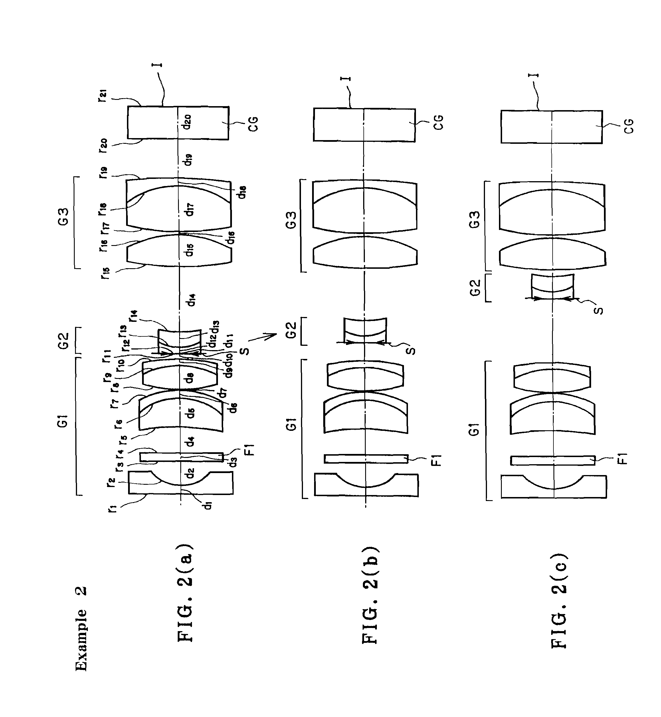
[0095]FIG. 2 is illustrative in section through the optical axis of the construction of the endoscope objective optical system according to Example 2. Numerical data on the example here will be set out in Table 3, given later, and the values of variation parameters in three viewing states: (a) normal viewing, (b) transient and (c) closest viewing are tabulated in Table 4, given later.

[0096]The endoscope objective optical system here is made up of, in order from the object side, a first group G1 of positive refracting power, a second group G2 of negative refracting power and a third group G3 of positive refracting power. The first group G1 consists of, in order from the object side, a piano-concave negative lens, a positive cemented lens in which a positive meniscus lens convex on its image side and a negative meniscus lens convex on its image side are cemented together, and a positive cemented lens in which a double-convex positive lens and a negative meniscus lens convex on its ima...

example 3

[0099]FIG. 3 is illustrative in section through the optical axis of the construction of the endoscope objective optical system according to Example 3. Numerical data on the example here will be set out in Table 5, given later, and the values of variation parameters in three viewing states: (a) normal viewing, (b) transient and (c) closest-range viewing are tabulated in Table 6, given later.

[0100]The endoscope objective optical system here is made up of, in order from the object side, a first group G1 of positive refracting power, a second group G2 of negative refracting power and a third group G3 of positive refracting power. The first group G1 consists of, in order from the object side, a piano-concave negative lens, a positive cemented lens in which a positive meniscus lens convex on its image side and a negative meniscus lens convex on its image side are cemented together, and a positive meniscus lens convex on its object side. The second group G2 consists of a negative cemented ...


PUM


Abstract

The invention relates to a high-performance imaging optical system that achieves a magnification high enough to be capable of microscopic viewing under an endoscope, and is compatible with high-definition imaging devices. The objective optical system comprises, at least in order from the object side, a positive, first group G1, a second group G2 and a third group G3. In association with an object point change, at least the second group G2 is moved along an optical axis. The objective optical system satisfies a condition with respect to an optical magnification β upon focusing on the closest range.

Description

BACKGROUND OF THE INVENTION[0001]The present invention relates generally to an objective optical system, and more specifically to an objective optical system having a focusing function. For instance, the invention relates to an endoscope objective lens capable of enlarged-scale proximity viewing, or a taking lens for digital or video cameras capable of microphotography, commercially marketable small-format cameras, and so on.[0002]In the medical endoscope field, there has recently been mounting demand for an optical system capable of implementing enlarged-scale closeup viewing for close examinations of lesions. Such an enlarged-scale view endoscope objective lens is broadly broken down into two types: one comprising +−+ three groups wherein the negative, second group moves for focusing on a near point, as set forth in Patent Publications 1, 2 and 3, and another comprising −+− three groups wherein the positive, second group moves for focusing, as disclosed in Patent Publication 4.[00...

Claims


Application Information

Patent Timeline
IPC IPC(8): G02B23/24G02B15/22
CPCG02B23/243
Inventor TAKATO, HIDEYASU
Owner OLYMPUS CORP
Why Eureka
Try Eureka