Electrolytic Cell for an Internal Combustion Engine

Inactive Publication Date: 2010-06-17
INNOVATIVE HYDROGEN SOLUTIONS
View PDF13 Cites 19 Cited by
  • Summary
  • Abstract
  • Description
  • Claims
  • Application Information

AI Technical Summary

Benefits of technology

[0031]Providing a power supply which is capable of adjusting the amperage supplied to the anode and cathode permits the rate of production of combustion enhancing gases to be controllably varied, for example to meet varying fuel demands in a vehicle internal combustion engine. More particularly, amperage supplied to the anode and cathode can be adjusted by shutting down on

Problems solved by technology

In general the prior art use of electrolysers are either far too complex to manufacture at a reasonable cost or pose certain safety risks due to the potential for explosions.
Many are inefficient and do not feed the combustion enhancing gases produced by the electrolyser to the engine in an efficient or reliable manner.
Furthermore, most known structures of anodes and cathodes are not well suited for production of combustion enhancing gases at a reliable rate or at a controllable rate as required by some specific applications, for example when used with an internal combustion engine on a vehicle with varying fuel demands.
As the solution is consumed by the cell however, the resulting fluid level in the cell will vary and will grea

Method used


Image

  • Electrolytic Cell for an Internal Combustion Engine
  • Electrolytic Cell for an Internal Combustion Engine
  • Electrolytic Cell for an Internal Combustion Engine

Examples


Embodiment Construction

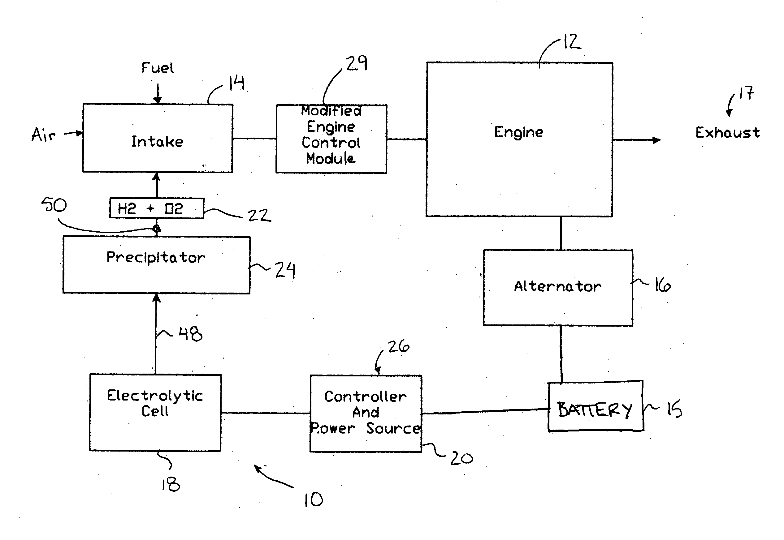
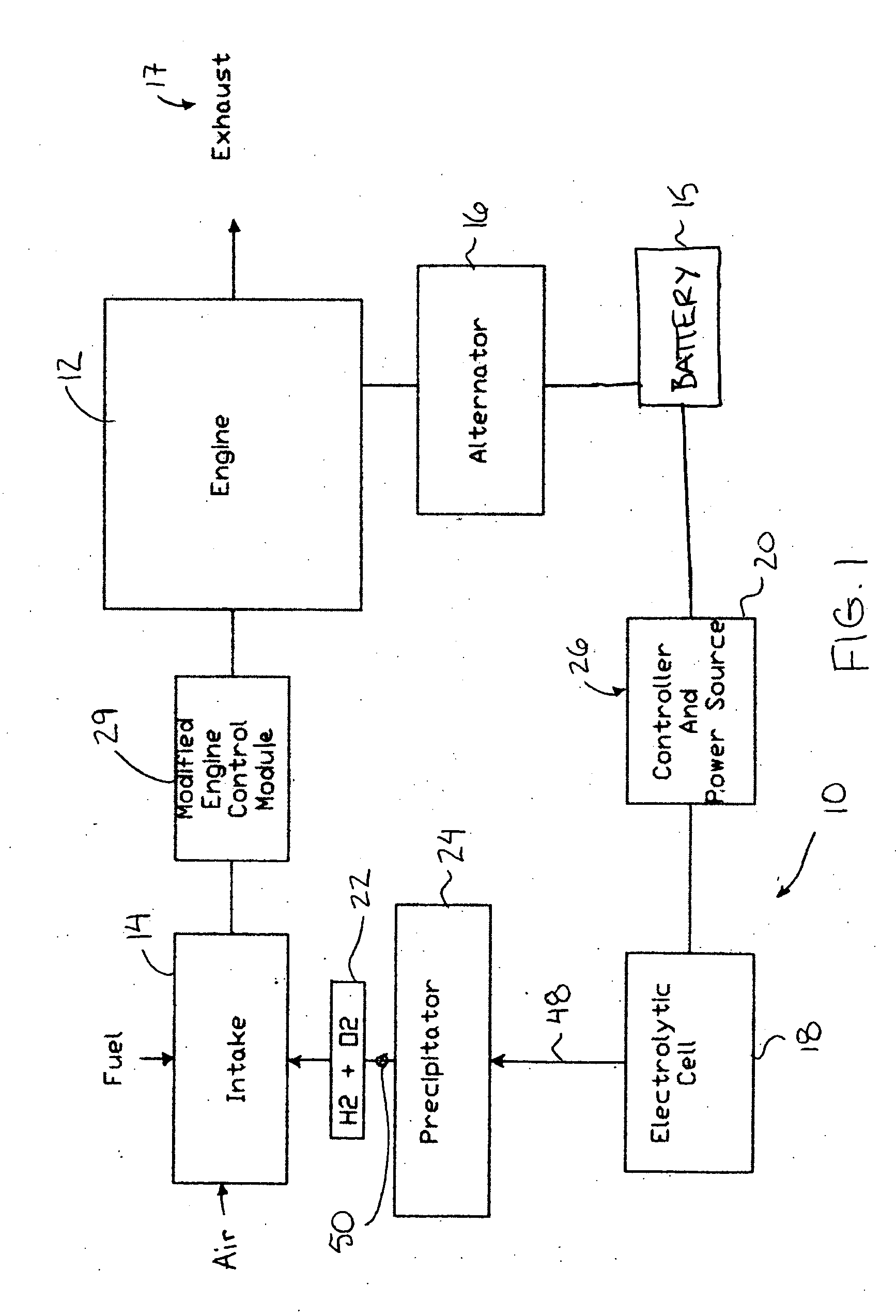
[0056]Referring to the accompanying figures there is illustrated an electrolyser system generally indicated by reference numeral 10. The system 10 is particularly suited for producing combustion enhancing gases for an internal combustion engine 12. Although various embodiments are shown in the accompanying Figures, the common features will first be described herein.

[0057]The engine 12 typically receives fuel from an onboard supply which is received through the intake 14 of the engine. Electrical power is generated by an onboard alternator 16 which is coupled to the engine. Generated electrical power or energy is stored in a battery 15. Combustion of the fuel within the engine produces exhaust 17.

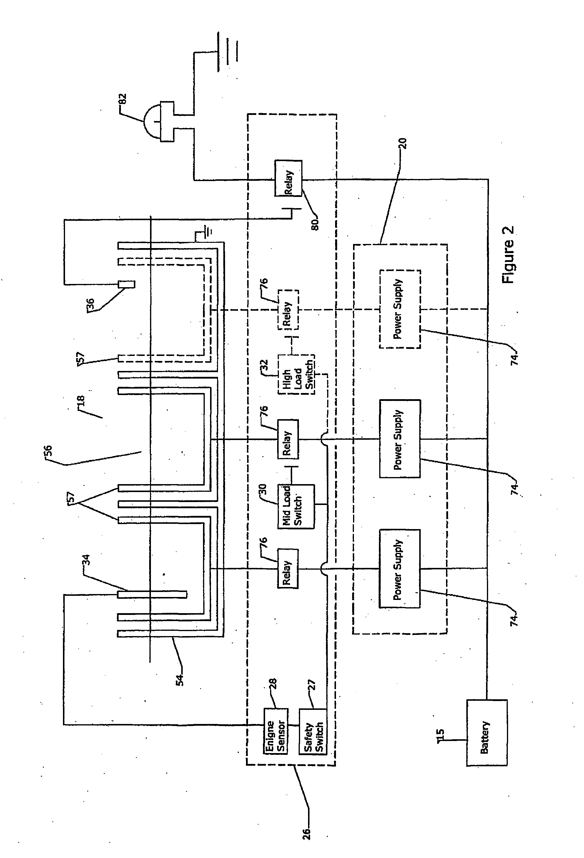
[0058]The electrolyser system 10 comprises an electrolytic cell 18 which receives power from a power source 20 which will be described in further detail below. The power source 20 receives power from the battery 15 and converts the power to a DC current which has been transformed to a range ...


PUM


Abstract

An electrolyser system produces combustion enhancing gas for communication with the intake of an internal combustion engine. An anode and a cathode are supported spaced apart from one another in a chamber filled with electrolytic solution with the cathode and the anode being nearest one another adjacent a bottom end of the chamber to concentrate the electrolysis activity adjacent the bottom end of the chamber. The electrolysis activity is therefore not significantly affected by varying levels of solution in the chamber. The anode comprises a plurality of independent units with respective independent power supplies. An amperage control selectively connects and disconnects the power supplies with the respective independent units of the anode for adjusting applied amperage across the solution and accordingly for varying the production rate of combustion enhancing gas responsive to engine demands.

Description

FIELD OF THE INVENTION[0001]The present invention relates to an electrolytic cell for use with an internal combustion engine, and more particularly relates to an electrolyser system using an electrolytic cell to produce gases for enhancing combustion in the engine.BACKGROUND[0002]It is known that the addition of hydrogen and oxygen gas to an internal combustion engine enhances combustion by reducing noxious emissions and improving mileage. It is further known that hydrogen and oxygen gases can be readily produced by electrolysis of water in an onboard electrolyser for a vehicle. Various related examples of electrolytic cells are listed in the following patents: U.S. Pat. No. 6,311,648 (Larocque), U.S. Pat. No. 4,875,988 (Aragon), U.S. Pat. No. 41,966,086 (Scoville), U.S. Pat. No. 5,178,118 (Nakamats), U.S. Pat. No. 4,368,696 (Reinhardt), U.S. Pat. No. 5,711,865 (Caesar), U.S. Pat. No. 4,627,897 (Tetzlaff et al), U.S. Pat. No. 4,111,160 (Talenti), U.S. Pat. No. 6,257,175 (Mosher et a...

Claims


Application Information

Patent Timeline
IPC IPC(8): F02B43/08
CPCC25B9/06C25B15/08C25B15/02C25B9/17
Inventor BOGERS, TIMOTHY DONALDWILLIAMS, JOSEPH C.
Owner INNOVATIVE HYDROGEN SOLUTIONS
Why Eureka
Try Eureka