Electrical energy amplifier system

a technology of amplifier system and electric energy, which is applied in the direction of dynamo-electric components, dynamo-electric machines, electrical apparatus, etc., can solve the problem that the motor of fossil fuels is generally very noisy

Inactive Publication Date: 2010-06-17
TYBURSKI ROBERT MICHAEL
View PDF3 Cites 4 Cited by
  • Summary
  • Abstract
  • Description
  • Claims
  • Application Information

AI Technical Summary

Problems solved by technology

Also fossil fuels motors are generally very noisy, solar devices require direct sunlight, Nuclear reactors require lead enclosures and highly trained personnel to handle a potentially dangerous device and wind devices require wind.

Method used


Image

  • Electrical energy amplifier system
  • Electrical energy amplifier system
  • Electrical energy amplifier system

Examples


Embodiment Construction

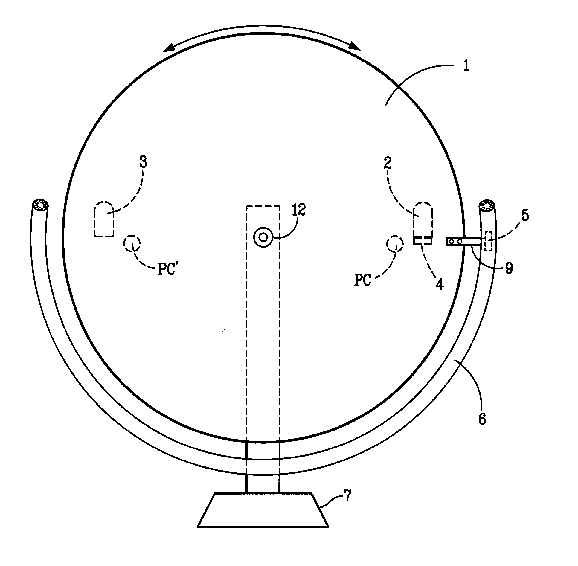
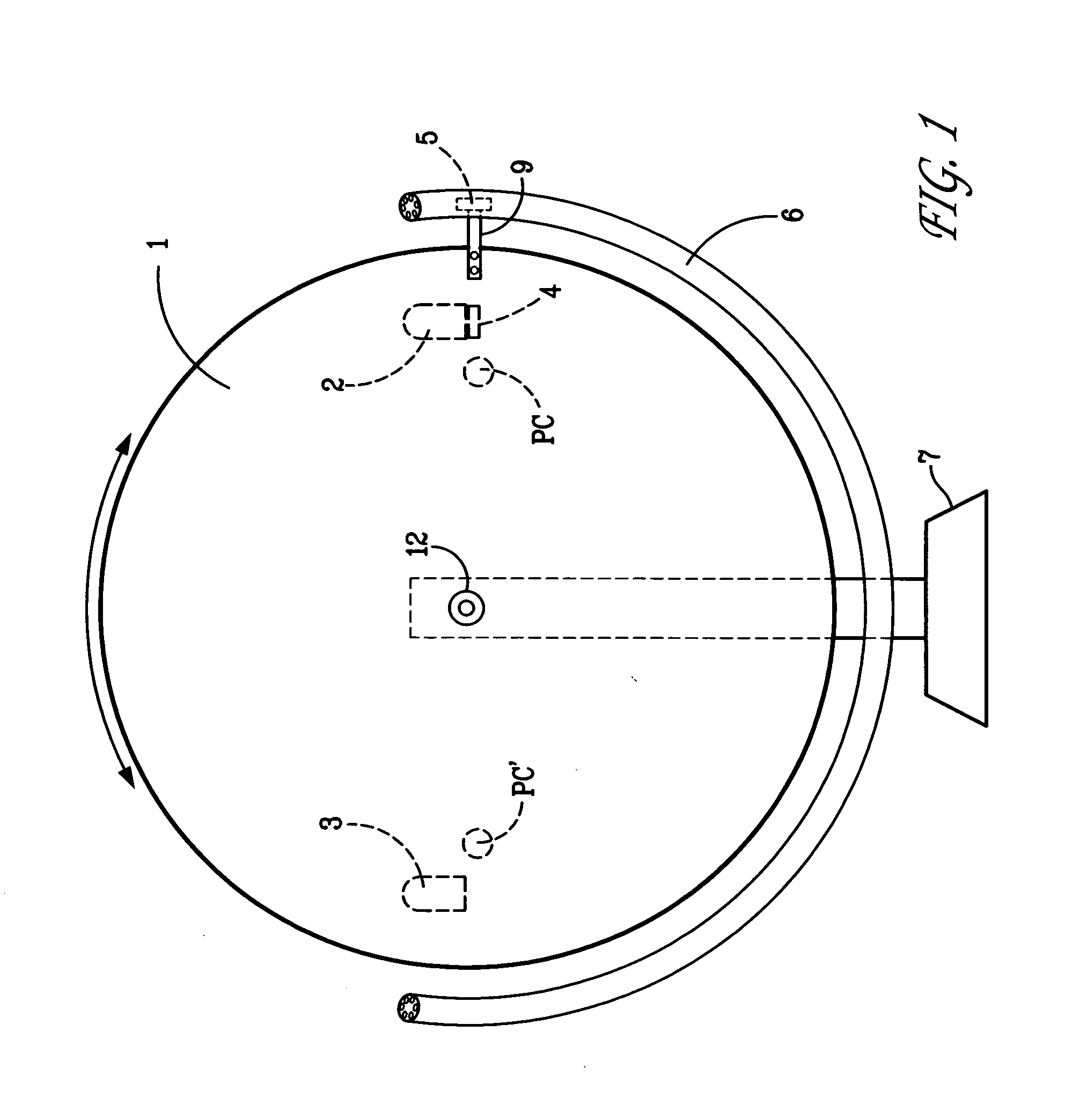
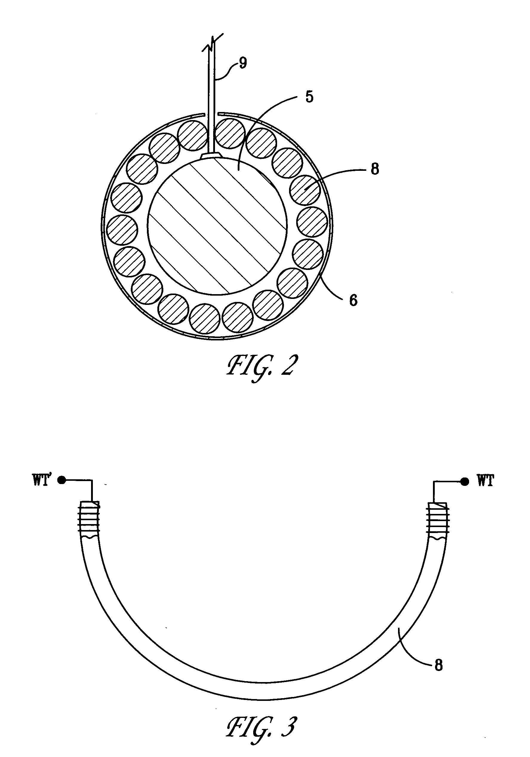
[0009]Referring to FIG. 1, an oscillating dick assembly comprising of a thin plastic disk 1, solenoid 2 and 3, photocells PC and PC′, latch bracket 4, rare earth magnet 5, molded plastic coil assembly 6, stand support 7, magnet connecting arm 9, low friction bearing assembly 12. Referring to FIG. 2, this is a section view of the molded coil assembly. It consists of the rare earth magnet 5, a molded plastic coil assembly 6 and wire wrapped plastic rods 8 and magnet connecting arm 9. Referring to FIG. 3, this is one wire wrapped plastic rod 8 with wire terminals WT and WT′. Referring to FIG. 4, this is a detailed drawing of the component parts relating to the solenoid assemble. It comprises of a DC operated solenoid 2, attached rubber shock absorbers 10, solenoid plunger 13, solenoid plunger tip magnet 11, latch bracket 4 that is attached to the oscillating plastic disk 1. Referring to FIG. 5, is the Electrical Energy Amplifier 14, Battery Electronic Interface 15, Storage Batteries 16...


PUM


Abstract

This invention has been developed to source low cost, reliable, clean electrical power. Its compact size, portability and self-sufficient drive means and associated generator make it ideal for numerous different applications where electrical power is required. The invention utilizes a partially rotating disk, a magnet connected to the rotating disk that moves through a chamber of copper wires and per Faraday's Law of Induction generates voltage and current. The output is connected to electronic circuitry that conditions the generated signal for battery storage. The batteries DC voltage is connected to an inverter that converts the DC battery voltage to an 117 VAC, 60 cycle electrical energy.

Description

REFERENCE TO PRIOR APPLICATION[0001]This application claims the benefit of provisional Application No. 61 / 201,868, filed Dec. 17, 2008 entitled Electrical Energy Amplifier System.BACKGROUND OF THE INVENTION[0002]Various portable electrical energy systems are in use and are known in this field of Patented Art. This invention describes a portable self-sufficient portable electrical energy system based on unique drive means, a generator and electrical storage means. This combination of components produces electrical energy every minute each day without any precondition of its location, without utilizing any external form of energy source such as gasoline, coal, wood, solar wind, steam and Nuclear, thereby eliminating the negative effects of pollution in the atmosphere. Also fossil fuels motors are generally very noisy, solar devices require direct sunlight, Nuclear reactors require lead enclosures and highly trained personnel to handle a potentially dangerous device and wind devices re...

Claims


Application Information

Patent Timeline
Patent Type & Authority Applications(United States)
IPC IPC(8): H02K7/18H02K53/00
CPCH02K53/00H02K35/02
Inventor TYBURSKI, ROBERT MICHAEL
Owner TYBURSKI ROBERT MICHAEL
Why Eureka
Try Eureka