System and method for fast retinal imaging

Active Publication Date: 2010-06-17
SLITLED LTD
View PDF6 Cites 32 Cited by
  • Summary
  • Abstract
  • Description
  • Claims
  • Application Information

AI Technical Summary

Benefits of technology

[0021]Accordingly, it is a broad object of the present invention to overcome the above disadvantages and limitations of the prior art by providing a system and a method for enabling taking a single picture of a three-dimensional ob

Problems solved by technology

One of the main difficulties today in ophthalmology is the lack of a good tomographic device which will give an instant picture of large parts of the retina and provide depth information at the same time.
This early discovery is difficult because of a few reasons.
Firstly, the optics of the eye hinder detection of details smaller than ten microns across, and usually even much coarser details are not seen.
While adaptive optics, in the future, might partially solve this problem, it is still limited by technology and by availability.
Unfortunately different schemes to get these depth pictures require some kind of scanning, which leads to other problems.
As the area and depth are divided into more resolution elements, it becomes nearly impossible to accumulate them all in a single picture.
Unfortunately, the patient's eye is a live object and i

Method used


Image

  • System and method for fast retinal imaging
  • System and method for fast retinal imaging
  • System and method for fast retinal imaging

Examples


Embodiment Construction

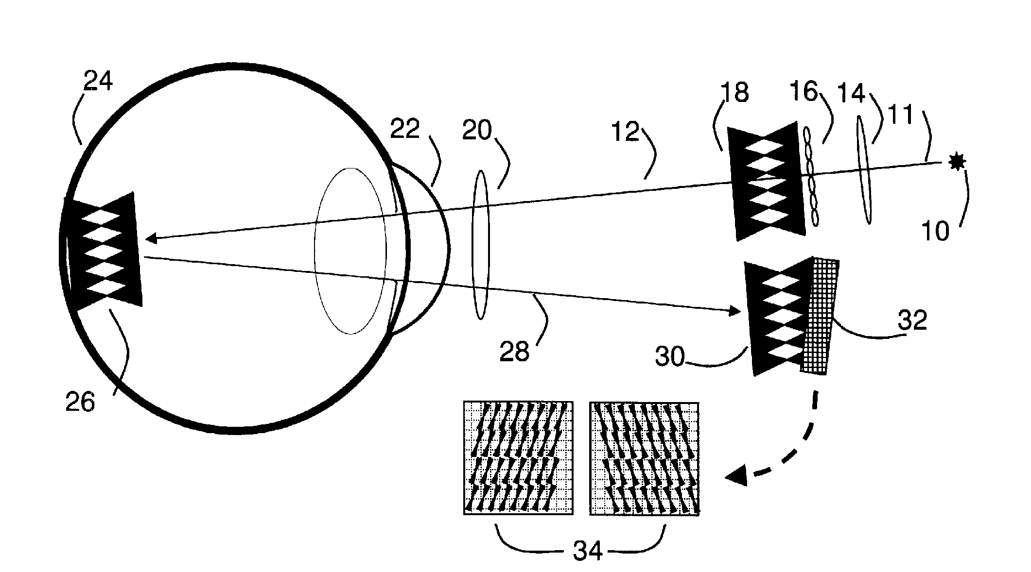
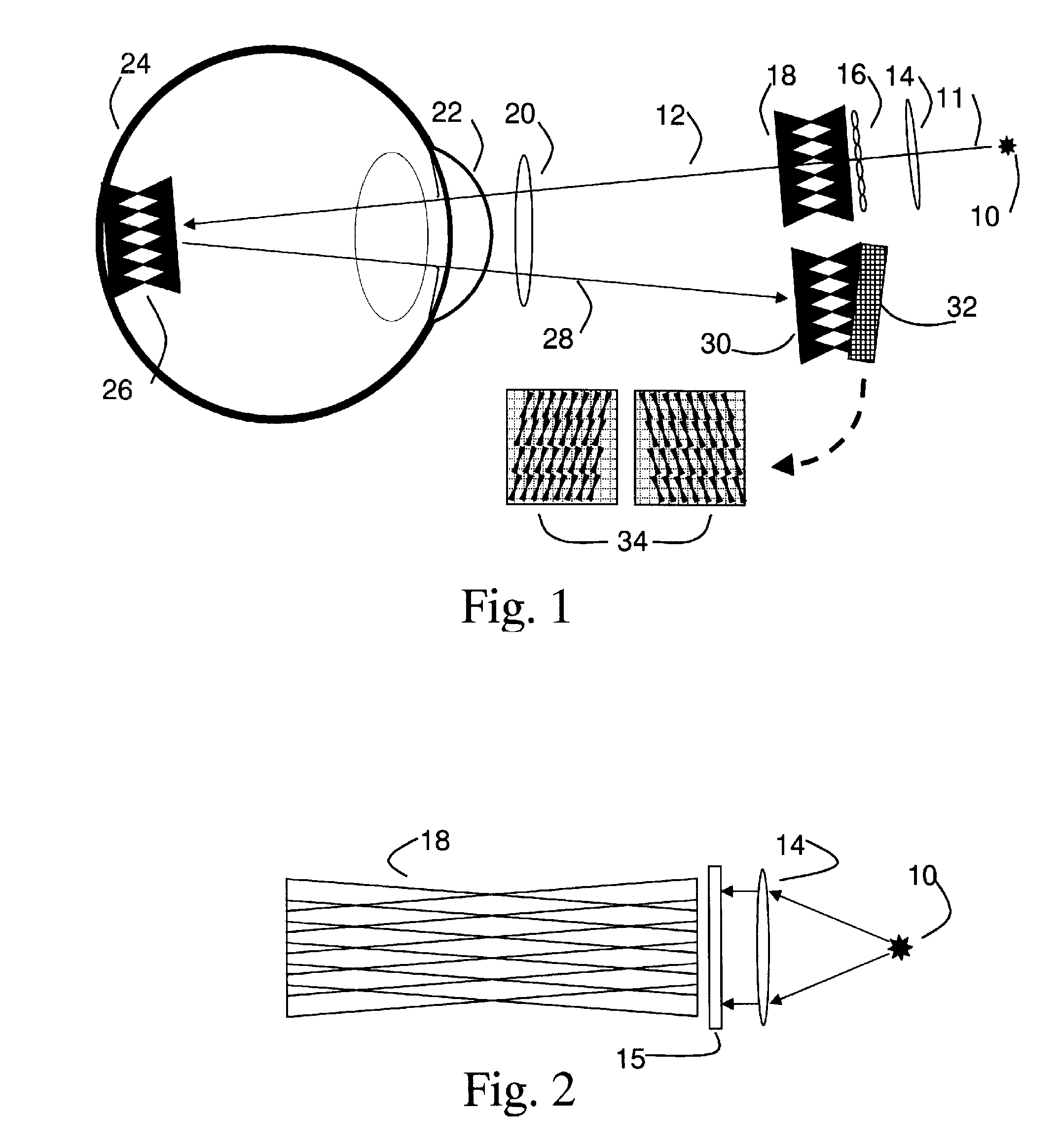
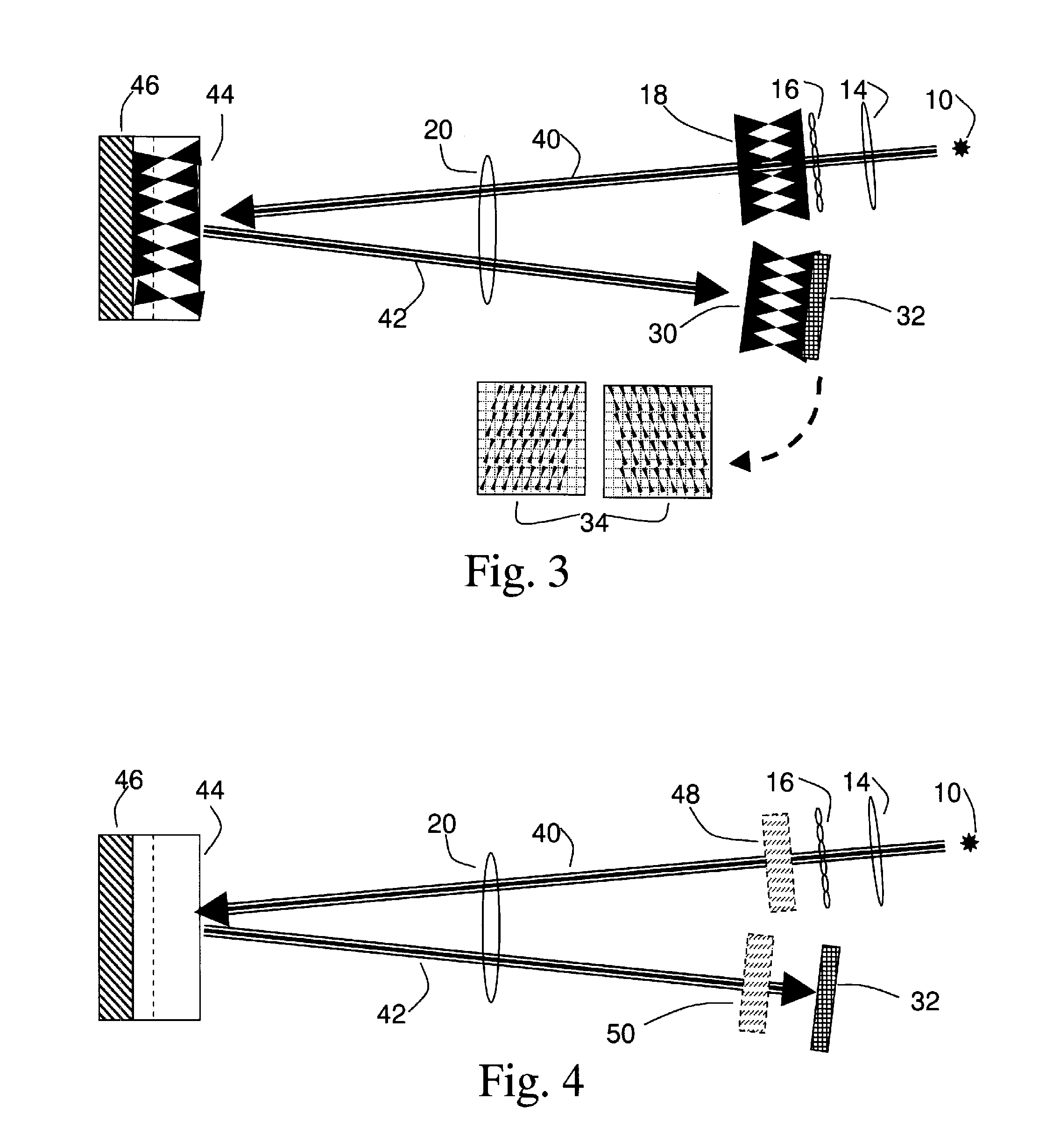
[0055]With specific reference now to the drawings in detail, it is stressed that the particulars shown are by way of example and for purposes of illustrative discussion of the preferred embodiments of the present invention only, and are presented in the cause of providing what is believed to be the most useful and readily understood description of the principles and conceptual aspects of the invention. In this regard, no attempt is made to show structural details of the invention in more detail than is necessary for a fundamental understanding of the invention, the description taken with the drawings making apparent to those skilled in the art how the several forms of the invention may be embodied in practice.

[0056]It is to be understood that the invention is not limited in its application to the details of construction and the arrangement of the components set forth in the following description or illustrated in the drawings. The invention is capable of other embodiments or of bein...


PUM


Abstract

An optical system and measurement method for imaging three-dimensional objects with low light scatter comprising at least one source of radiation; a radiation projection means for creating a set of foci through a volume of an object; and a means for imaging the returned light from the set of foci on at least one camera, wherein the imaging of the volume of the object is at a different angle from the projection, allowing for detection of the returned light on separate camera pixels. The measurement method further comprises projecting a longitudinal grid of elongated foci through the volume of an object; imaging returned light from the object at a different angle on at least one camera, so as to avoid overlapping the elongated images; and analyzing the imaged, returned light to yield depth information of the object at a multiplicity of points.

Description

FIELD OF THE INVENTION[0001]The present invention generally relates to the field of imaging three-dimensional objects with low light scatter, and more particularly, to a system and method for fast retinal imaging by parallel projections and extraction of parameters from such retinal images.BACKGROUND OF THE INVENTION[0002]One of the main difficulties today in ophthalmology is the lack of a good tomographic device which will give an instant picture of large parts of the retina and provide depth information at the same time. There are cameras which scan through the retina and there are cameras which take one or more images. Thus the choice of the ophthalmologist is between having good depth information in a few and sometimes unknown locations or a superficial picture of larger areas of the retina, but without depth information.[0003]Such information is necessary in order to prevent some of the most blinding diseases, if only detected early enough. The prevalence of retinal diseases is...

Claims


Application Information

Patent Timeline
IPC IPC(8): A61B3/14G01B21/18
CPCA61B3/12A61B5/0073G01B11/22H04N7/18G06T7/0057G06T2207/30041A61B3/14G01B11/2513G06T7/521
Inventor RIBAK, EREZ
Owner SLITLED LTD
Why Eureka
Try Eureka