Motion control servo loop apparatus

a technology of servo loop and servo motor, which is applied in the direction of electric controllers, program control, dynamo-electric converter control, etc., can solve the problems of inability to respond to the change in the system in real-time, failure to improve system performance, and unstable control system, so as to improve the transient response speed, eliminate steady-state errors, and improve the effect of response speed

Active Publication Date: 2010-06-17
IND TECH RES INST
View PDF5 Cites 19 Cited by
  • Summary
  • Abstract
  • Description
  • Claims
  • Application Information

AI Technical Summary

Benefits of technology

[0006]In view of the above, the present invention provides a motion control servo loop apparatus comprising a proportional-integral-derivative (PID) control loop having an integral control module using a digital differential analyzer (DDA) algorithm to enhance the response speed, eliminate the steady-state error, improve the transient response and compensate the delay of a controlled system.

Problems solved by technology

Therefore, it fails to improve system performance such as the response speed and the steady-state error, and is only suitable for low-end control.
Therefore, it fails to respond to the change in the system in real-time.
If the parameters such as the integral gain and the integral time are set too large, the controlled system will be unstable due to oscillation caused by rapidly increased accumulated error.
The servo significantly lags under high speed control, which causes slow response, affects the tracking accuracy and is not useful in high precision control.

Method used


Image

  • Motion control servo loop apparatus
  • Motion control servo loop apparatus
  • Motion control servo loop apparatus

Examples


Embodiment Construction

[0012]The present invention can be exemplified by but not limited to the preferred embodiment as described hereinafter.

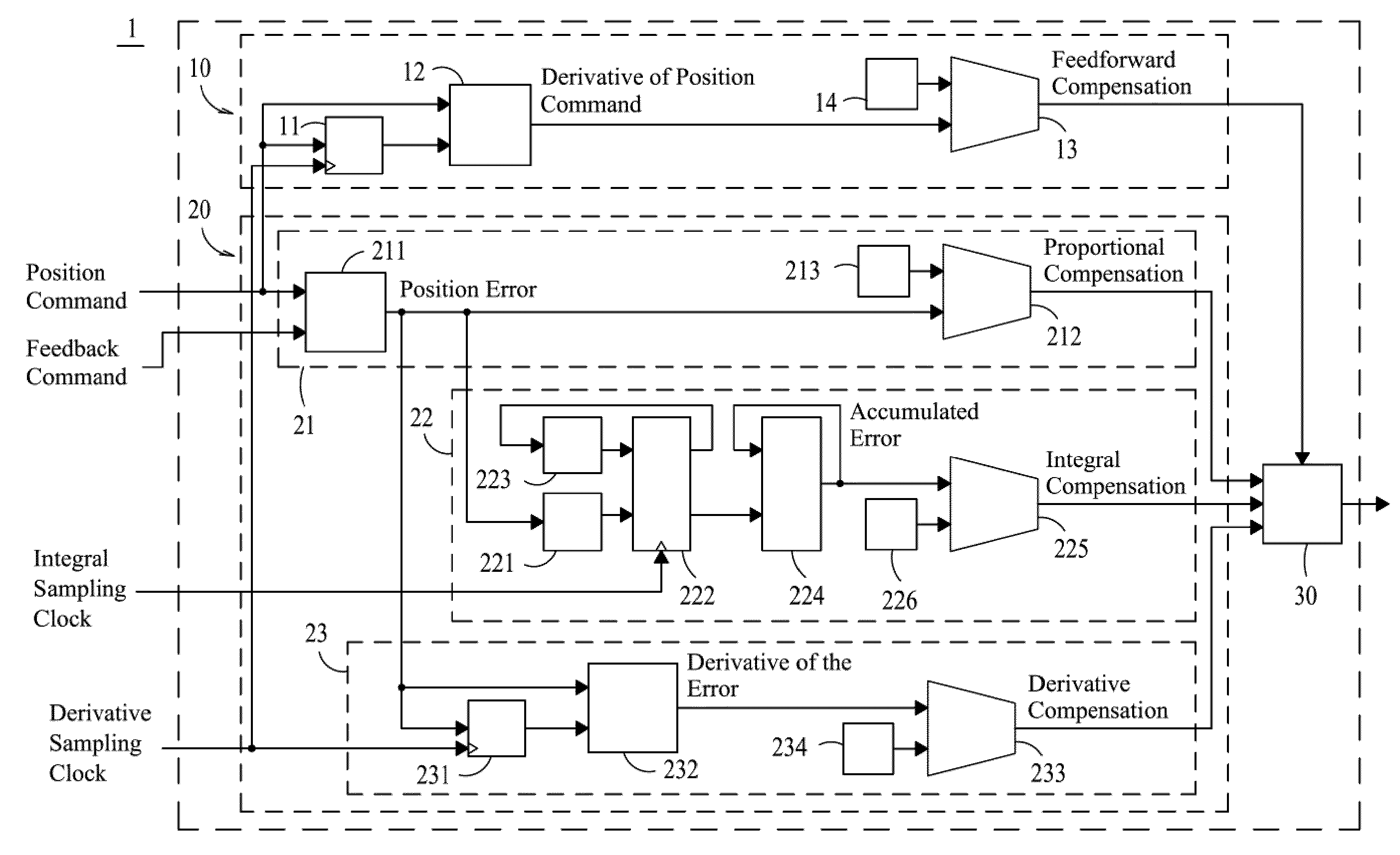
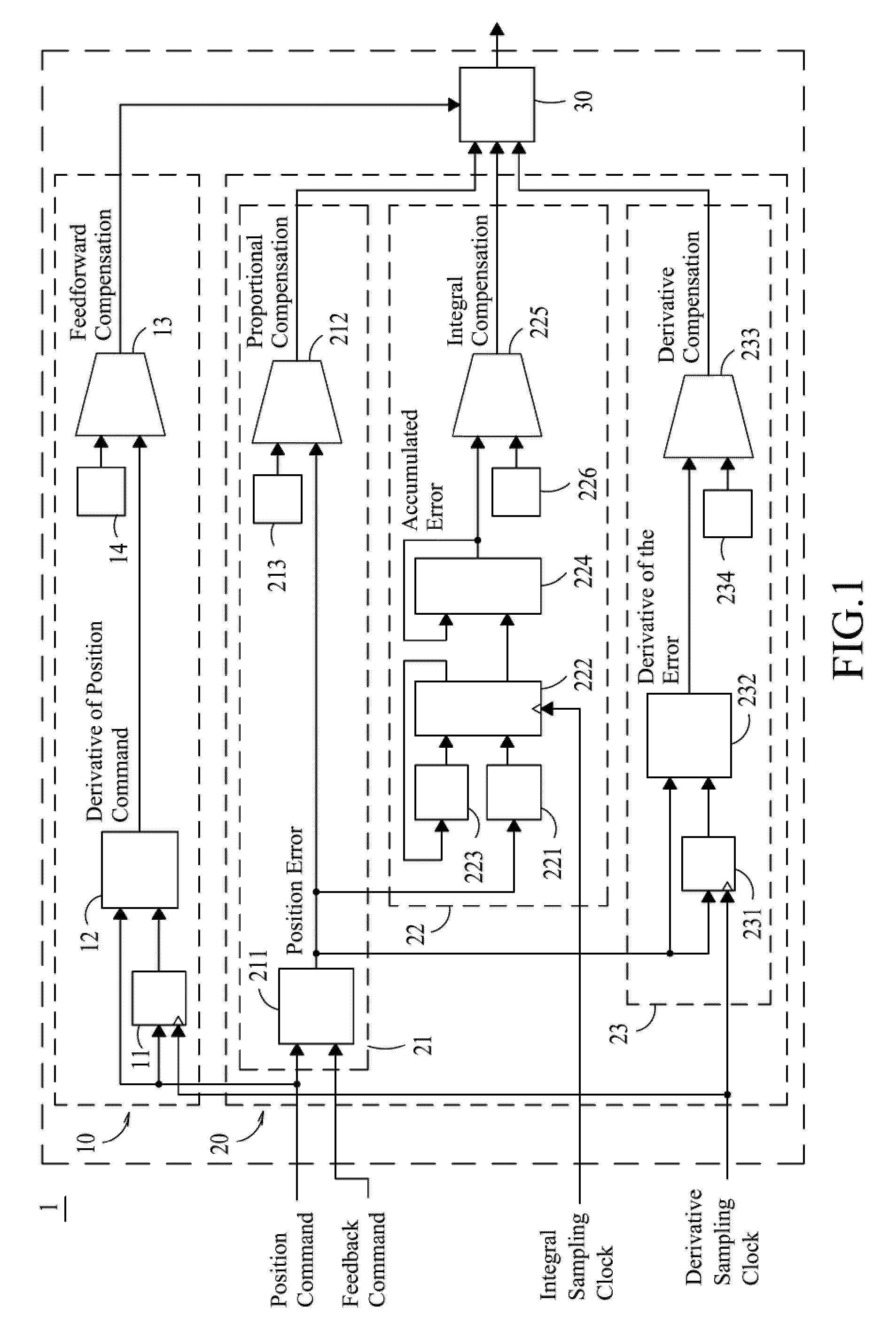
[0013]Please refer to FIG. 1, which is a schematic diagram of a motion control servo loop apparatus according to the present invention. The motion control servo loop apparatus comprises a feed-forward control module 10, a proportional-integral-derivative (PID) control loop 20 and a compensation adder 30.

[0014]The feed-forward control module 10 uses a register 11 and a subtractor 12 to differentiate a position command and generate a derivative of position command, which is multiplied with a feed-forward gain coefficient 14 by a multiplier 13 to generate a feed-forward compensation. The feed-forward compensation is then input into the compensation adder 30. The feed-forward control module 10 differentiates the position command, which is corrected by the feed-forward controller before the target signal is input into a motor driver (not shown), so that the signal input ...


PUM


Abstract

A motion control servo loop apparatus, comprising: a feed-forward control module, and a proportional-integral-derivative (PID) control loop and a compensation adder. The feed-forward control module is capable of generating a feed-forward compensation. The PID control loop further comprises: a proportional control module, an integral control module and a derivative control module. The proportional control module is capable of generating a proportional compensation. The derivative control module is capable of generating a derivative compensation. The integral control module uses a digital differential analyzer (DDA) algorithm to perform integration for accumulated errors with respect to each sampling clock at each DDA pulse and thus output an accumulated error, which is then processed to generate an integral compensation. Thereafter, the compensation adder receives the feed-forward compensation, the proportional compensation, the integral compensation and the derivative compensation to calculate a position error compensation for a motor driver.

Description

FIELD OF THE INVENTION[0001]The present invention generally relates to a motion control servo loop apparatus and, more particularly, to a motion control servo loop apparatus comprising a proportional-integral-derivative (PID) control loop having an integral control module using a digital differential analyzer (DDA) algorithm to enhance the response speed, eliminate the steady-state error, improve the transient response and compensate the delay of a controlled system.BACKGROUND OF THE INVENTION[0002]Motion control is a common fundamental technology for all machine controllers to control the speed, position and torque of a motor used on various machines for driving cutting tools or chucks in the 3-D space to perform cutting, manufacturing, assembly, fetching and other automated motions along an expected trajectory with expected speed at expected time. There are two types of conventional motion control servo loop: open-loop control, and closed loop control using proportional-integral-d...

Claims


Application Information

Patent Timeline
Patent Type & Authority Applications(United States)
IPC IPC(8): G05B13/02
CPCG05B11/42G05B2219/41434G05B2219/41199
Inventor CHEN, YING-MINCHEN, WEN-CHUANHUANG, JING-YIWU, CHENG-XUELIN, CHIA-CHINGSHEN, WAN-KAI
Owner IND TECH RES INST
Why Eureka
Try Eureka