Engine Misfire Identification Device for Internal Combustion Engine, Vehicle Equipped With the Same and Method of Engine Misfire Identification

a technology of misfire identification and internal combustion engine, which is applied in the direction of machines/engines, electric control, instruments, etc., can solve the problems of difficult identification of engine misfire in conventional engine misfire identification methods, and difficulty in identifying engine misfires, and achieve the effect of improving accuracy

Inactive Publication Date: 2010-06-17
TOYOTA JIDOSHA KK
View PDF8 Cites 26 Cited by
  • Summary
  • Abstract
  • Description
  • Claims
  • Application Information

AI Technical Summary

Benefits of technology

[0040]In the second engine misfire identification method for an internal combustion engine of the present invention in an aspect based on the use of a high-pass filter as this second technique, the second technique may be a technique for making an identification on an engine misfire on the basis of an identification parameter for high loads, which is obtained by integrating an absolute value of a differentiated value of the angular velocity after filtering in a first prescribed range, when the internal combustion engine is operating under a high load of not less than a prescribed load, and an identification is made on an engine misfire on the basis of an identification parameter for low loads, which is obtained by integrating the angular velocity after filtering in a second prescribed range, when the internal combustion engine is operating under a low load of less than the prescribed load. Accordingly, even in a case where the internal combustion engine is operating under a high load of not less than a prescribed load when the drive point of the internal combustion engine belongs to a resonance region or even in a case where the internal combustion engine is operating under a low load of less than the prescribed load, it is possible to more appropriately identify an engine misfire in the internal combustion engine.
[0041]Additionally, in the second engine misfire identification method for an internal combu

Problems solved by technology

When damping control is being performed as in the above-described apparatus, it is difficult to identify an engine misfire in conventional engine misfire identification methods.
For example, when an engine is connected to a transmission and the l

Method used


Image

  • Engine Misfire Identification Device for Internal Combustion Engine, Vehicle Equipped With the Same and Method of Engine Misfire Identification
  • Engine Misfire Identification Device for Internal Combustion Engine, Vehicle Equipped With the Same and Method of Engine Misfire Identification
  • Engine Misfire Identification Device for Internal Combustion Engine, Vehicle Equipped With the Same and Method of Engine Misfire Identification

Examples


first embodiment

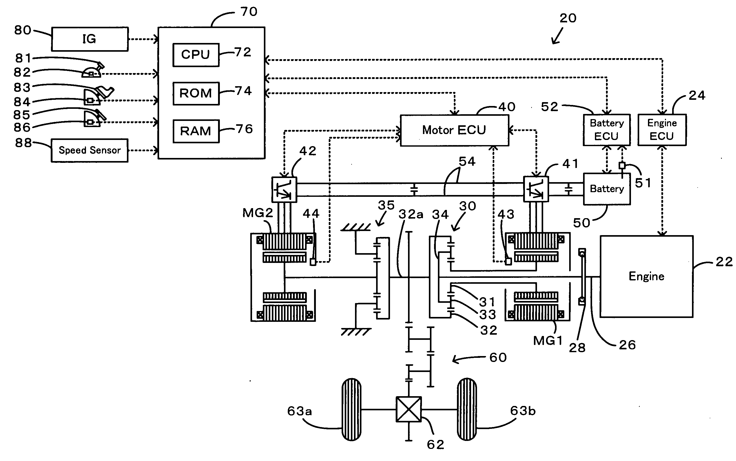
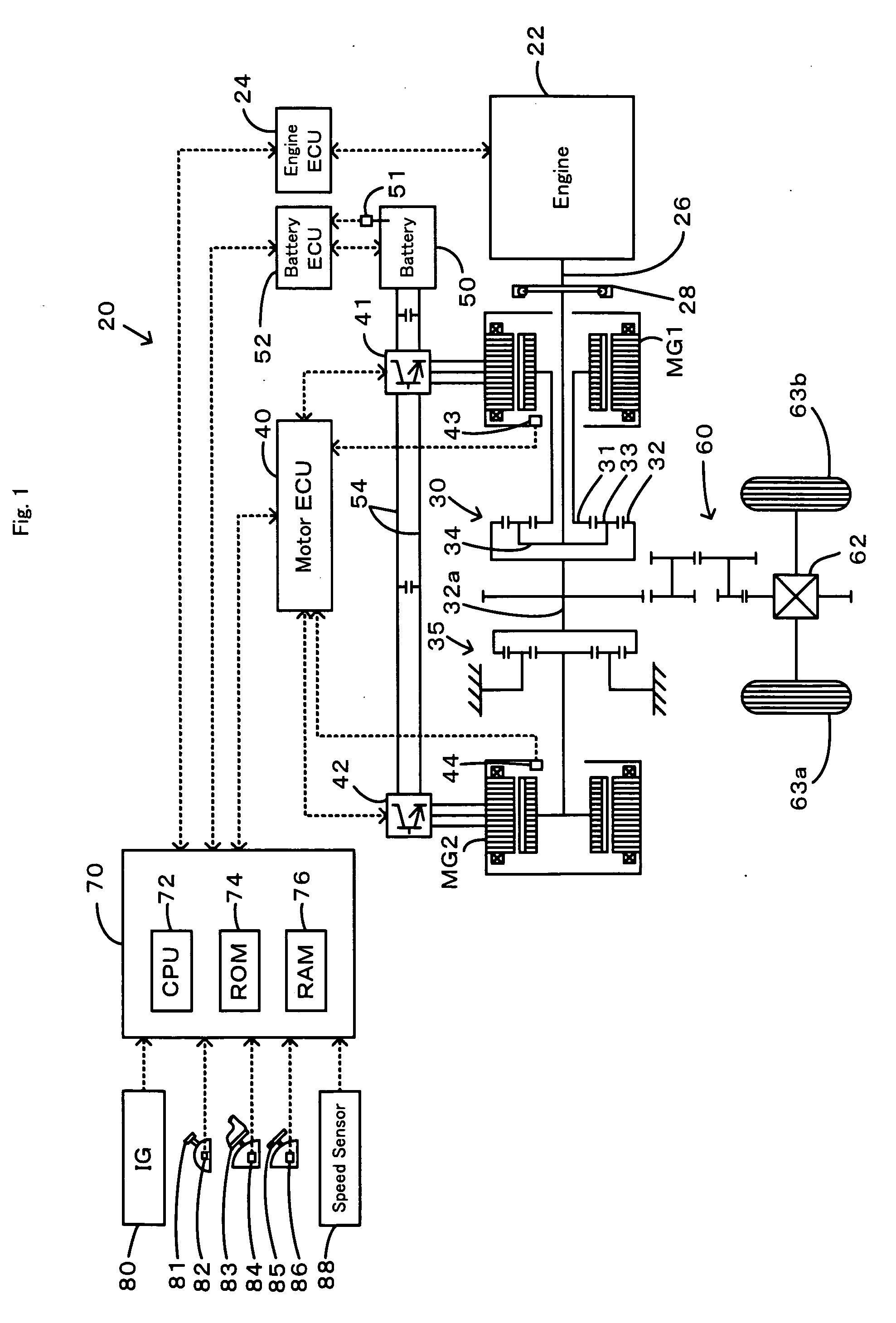
[0070]The hybrid vehicle 20 of the first embodiment thus constructed calculates a torque demand to be output to the ring gear shaft 32a functioning as the drive shaft, based on observed values of a vehicle speed V and an accelerator opening Acc, which corresponds to a driver's step-on amount of an accelerator pedal 83. The engine 22 and the motors MG1 and MG2 are subjected to operation control to output a required level of power corresponding to the calculated torque demand to the ring gear shaft 32a. The operation control of the engine 22 and the motors MG1 and MG2 selectively effectuates one of a torque conversion drive mode, a charge-discharge drive mode, and a motor drive mode. The torque conversion drive mode controls the operations of the engine 22 to output a quantity of power equivalent to the required level of power, while driving and controlling the motors MG1 and MG2 to cause all the power output from the engine 22 to be subjected to torque conversion by means of the powe...

second embodiment

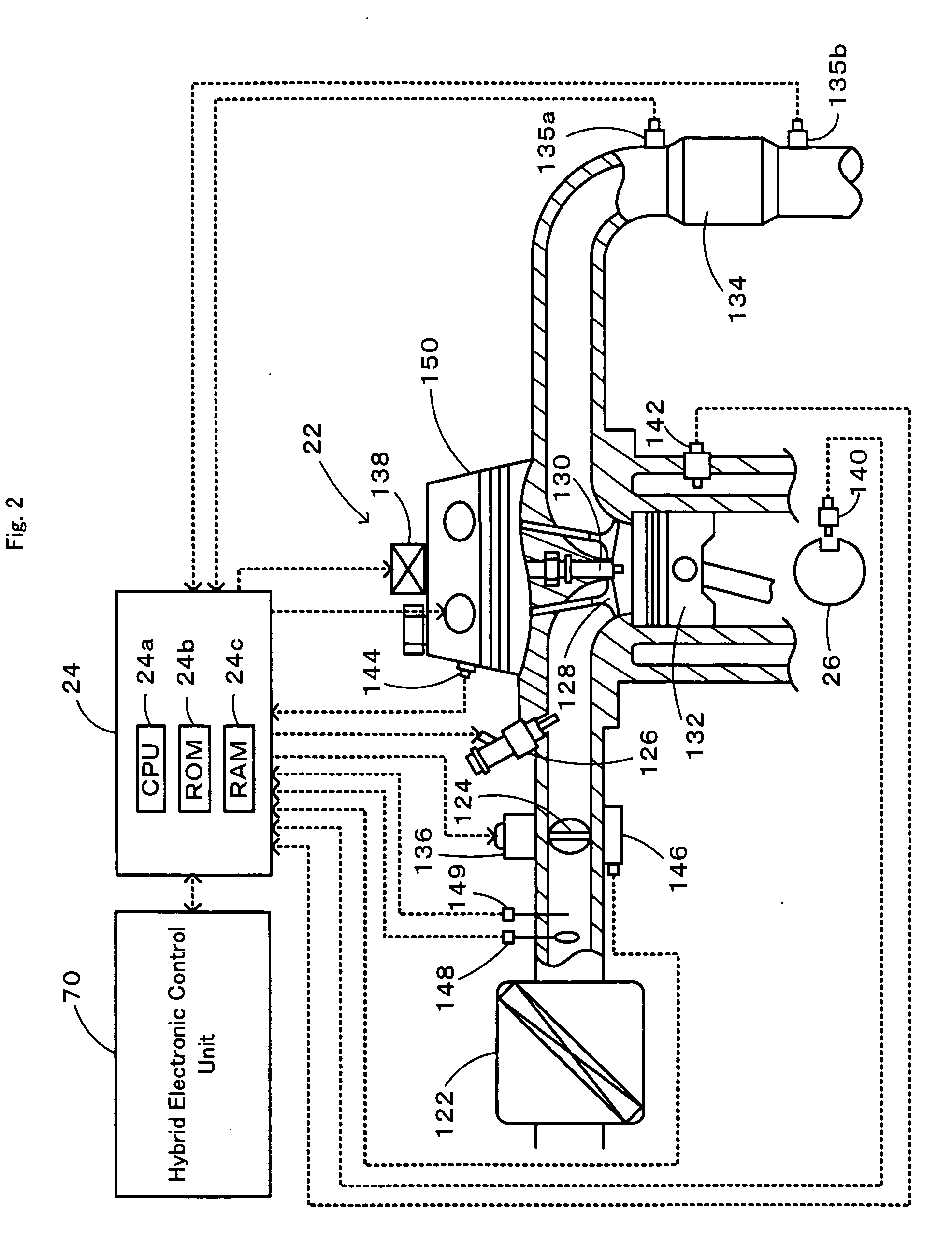
[0095]In the engine misfire identification device for an internal combustion engine mounted on the hybrid vehicle 20D of the second embodiment, when the resonance-region engine misfire detection processing of FIG. 13 has been executed by an engine ECU 24, a CPU 24a of the engine ECU 24 first executes processing of inputting the rotation speed Ne and torque Te of an engine 22, a catalyst warming-up flag Fc, the 10-degree rotation angular velocity ω10, which is a rotation angular velocity occurring each time a crankshaft 26 rotates through 10 degrees and computed by the ω10 computation processing schematically represented in FIG. 14 (Step S500). In this connection, the catalyst warming-up flag Fc is a flag that indicates whether or not the engine 22 is operating in a prescribed operating condition in order to warm up a catalyst filled in a purifier 134 of the engine 22. The value 1 is set by a hybrid electronic control unit 70 when the engine 22 is operating in a prescribed operating ...

third embodiment

[0112]In the engine misfire identification device for an internal combustion engine mounted on the hybrid vehicle 20E of the third embodiment, when the resonance-region engine misfire detection processing of FIG. 18 has been executed by an engine ECU 24, a CPU 24a of the engine ECU first executes processing of inputting the rotation speed Ne of an engine 22 and the 10-degree rotation angular velocity ω10, which is a rotation angular velocity occurring each time a crankshaft 26 rotates through 10 degrees, and computed by the ω10 computation processing schematically represented in FIG. 14 (Step S800). The ω10 computation processing was also described above.

[0113]Subsequently, a high-pass filter is set on the basis of the rotation speed Ne of the engine 22 (Step S810), and the angular velocity after filtering ω10f is obtained by applying the set high-pass filter to the 10-degree rotation angular velocity ω10 (Step S820). In this connection, it is possible to set the high-pass filter by...


PUM


Abstract

An engine misfire is identified by ordinary engine misfire detection processing when the operating condition of an engine comprising a rotation speed Ne and a torque Te does not belong to a resonance region of a rear portion including a damper as a torsion element (S120), and an engine misfire is identified by resonance-region engine misfire detection processing, which is different from the ordinary engine misfire detection processing, when the operating condition of an engine belongs to a resonance region of a rear portion including a damper (S130). This enables an engine misfire to be identified more reliably and with good accuracy regardless of whether the operating condition of an engine belongs to a resonance region of a rear portion including a damper.

Description

TECHNICAL FIELD[0001]The present invention relates to an engine misfire identification device for an internal combustion engine, a vehicle equipped with this engine misfire identification device, and an engine misfire identification method. More particularly, the invention relates to an engine misfire identification device that identifies an engine misfire in a multiple-cylinder internal combustion engine in which an output shaft is connected to a rear portion via a torsion element, a vehicle equipped with an internal combustion engine and this engine misfire identification device, and an engine misfire identification method for identifying an engine misfire in a multiple-cylinder internal combustion engine in which an output shaft is connected to a rear portion via a torsion element.BACKGROUND ART[0002]As such engine misfire identification device of this kind for an internal combustion engine, there has been proposed engine misfire identification device in a vehicle in which a moto...

Claims


Application Information

Patent Timeline
IPC IPC(8): G06F19/00F02D45/00
CPCG01M15/11F02D29/00F02D35/02F02D45/00
Inventor SUZUKI, TAKASHI
Owner TOYOTA JIDOSHA KK
Why Eureka
Try Eureka