Cmas mitigation compositions, environmental barrier coatings comprising the same, and ceramic components comprising the same

a technology of magnesium aluminosilicate and composition, which is applied in the direction of machine/engine, water-setting substance layered product, and silicate, etc., can solve the problems of significant material loss, or recession, over the lifetime of an engine component, and the accumulation of cmas on components located in higher temperature sections of gas turbine engines

Active Publication Date: 2010-06-24
GENERAL ELECTRIC CO
View PDF33 Cites 38 Cited by
  • Summary
  • Abstract
  • Description
  • Claims
  • Application Information

AI Technical Summary

Benefits of technology

[0014]Embodiments herein also generally relate to high temperature components having CMAS mitigation capability comprising an environmental barrier coating including a bond coat layer; an optional silica layer; at least one transition layer; an optional outer layer; and a separate CMAS mitigation layer comprising a CMAS mitigation composition selected from the group consisting of rare earth elements, rare earth oxides, zirconia, hafnia partially or fully stabilized with alkaline earth or rare earth elements, zirconia partially or fully stabilized with alkaline earth or rare earth elements, magnesium oxide, cordierite, aluminum phosphate, magnesium silicate, and combinations thereof.

Problems solved by technology

However, as operating temperatures increase, the high temperature durability of the components of the engine must correspondingly increase.
This oxidation / volatilization process can result in significant material loss, or recession, over the lifetime of an engine component.
From about 10% to about 40% porosity, the layer can display mechanical integrity, but hot gases can penetrate through the coating layer damaging the underlying EBC.
Unfortunately, deposits of CMAS have been observed to form on components located within higher temperature sections of gas turbine engines, particularly in combustor and turbine sections.
It is also known that the reaction byproducts formed by the interaction of BSAS and CMAS can be detrimental to EBCs, as well as susceptible to volatilization in the presence of steam at high temperatures.
Such volatilization can result in the loss of coating material and protection for the underlying component.
Thus, it is expected that the presence of CMAS will interact with the EBC, thereby jeopardizing the performance of the component along with component life.

Method used


Image

  • Cmas mitigation compositions, environmental barrier coatings comprising the same, and ceramic components comprising the same
  • Cmas mitigation compositions, environmental barrier coatings comprising the same, and ceramic components comprising the same
  • Cmas mitigation compositions, environmental barrier coatings comprising the same, and ceramic components comprising the same

Examples


Embodiment Construction

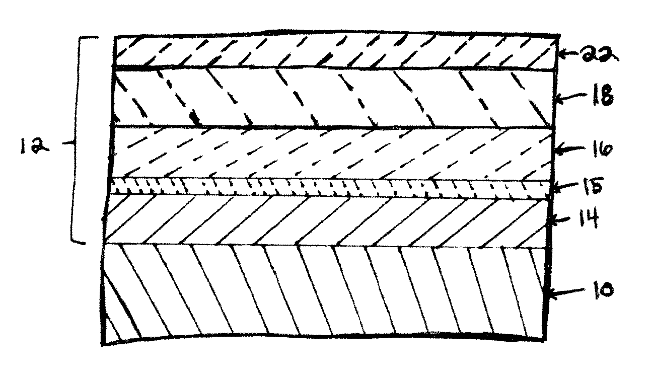
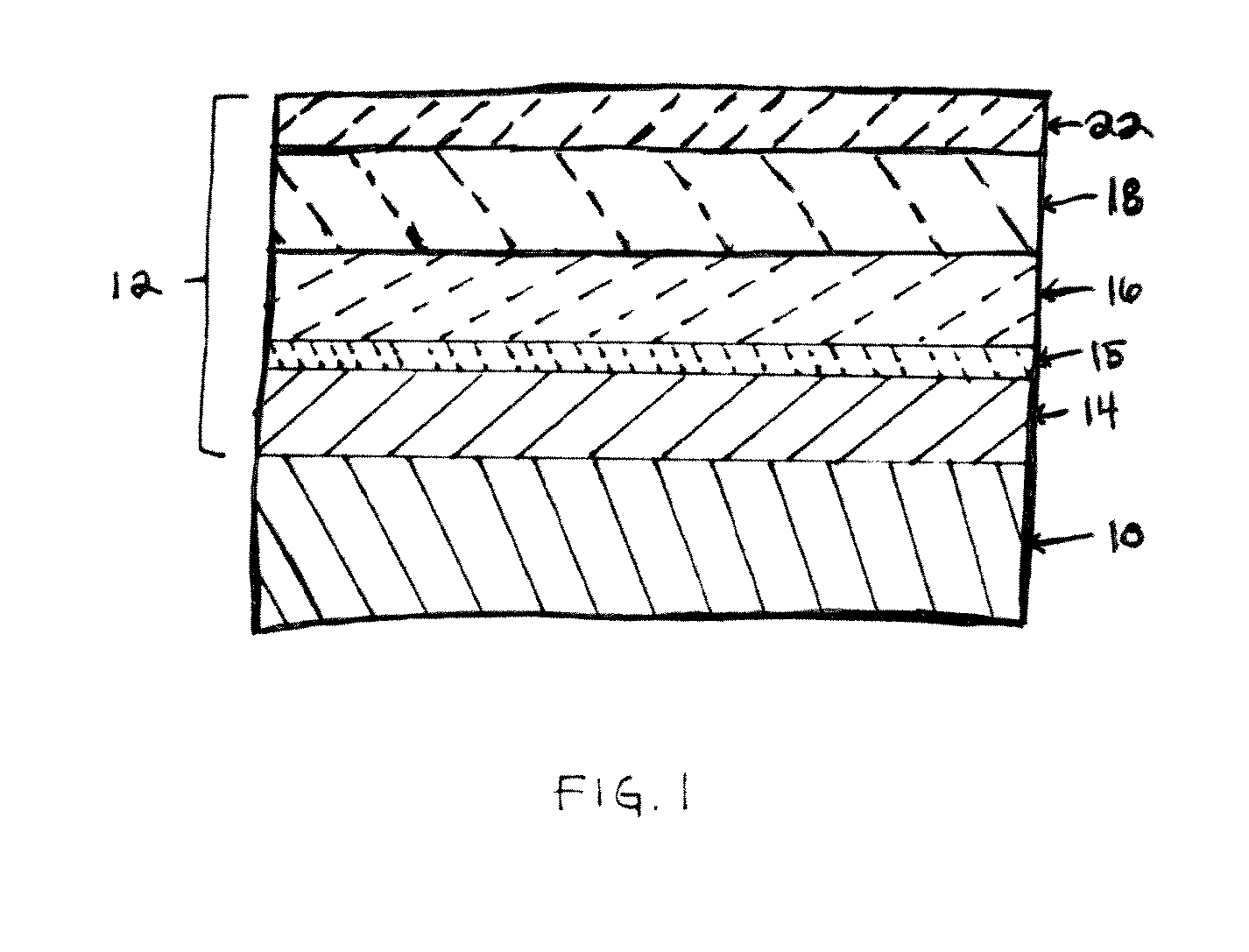
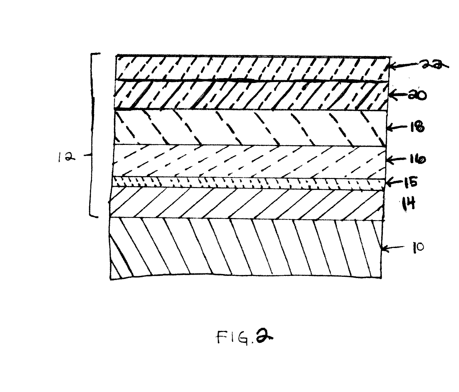
[0021]Embodiments described herein generally relate to CMAS mitigation compositions, as well as EBCs and ceramic components comprising the same.

[0022]The CMAS mitigation compositions described herein may be suitable for use in conjunction with EBCs for substrates comprising CMCs, and monolithic ceramics. As used herein, “CMCs” refers to silicon-containing, or oxide-oxide, matrix and reinforcing materials. Some examples of CMCs acceptable for use herein can include, but should not be limited to, materials having a matrix and reinforcing fibers comprising non-oxide silicon-based materials such as silicon carbide, silicon nitride, silicon oxycarbides, silicon oxynitrides, and mixtures thereof. Examples include, but are not limited to, CMCs with silicon carbide matrix and silicon carbide fiber; silicon nitride matrix and silicon carbide fiber; and silicon carbide / silicon nitride matrix mixture and silicon carbide fiber. Furthermore, CMCs can have a matrix and reinforcing fibers comprise...


PUM

PropertyMeasurementUnit
thicknessaaaaaaaaaa
thicknessaaaaaaaaaa
thicknessaaaaaaaaaa

Abstract

Calcium magnesium aluminosilicate (CMAS) mitigation compositions selected from rare earth elements, rare earth oxides, zirconia, hafnia partially or fully stabilized with alkaline earth or rare earth elements, zirconia partially or fully stabilized with alkaline earth or rare earth elements, magnesium oxide, cordierite, aluminum phosphate, magnesium silicate, and combinations thereof when the CMAS mitigation composition is included as a separate CMAS mitigation layer in an environmental barrier coating for a high temperature substrate component.

Description

STATEMENT OF GOVERNMENT RIGHTS[0001]This invention was made, at least in part, with a grant from the Government of the United States (Contract No. N00019-04-C-0093, from the Department of the Navy). The Government may have certain rights to the invention.TECHNICAL FIELD[0002]Embodiments described herein generally relate to calcium magnesium aluminosilicate (CMAS) mitigation compositions, environmental barrier coatings comprising the same, and ceramic components comprising the same.BACKGROUND OF THE INVENTION[0003]Higher operating temperatures for gas turbine engines are continuously being sought in order to improve their efficiency. However, as operating temperatures increase, the high temperature durability of the components of the engine must correspondingly increase. Significant advances in high temperature capabilities have been achieved through the formulation of iron, nickel, and cobalt-based superalloys. While superalloys have found wide use for components used throughout gas...

Claims


Application Information

Patent Timeline
Patent Type & Authority Applications(United States)
IPC IPC(8): F01D9/00B32B9/00C01B33/26C01F17/00F01D5/14
CPCC04B41/009C23C28/042C04B41/89F01D5/288C04B41/52F05D2300/611C04B41/5096C04B41/5035C04B41/5024C04B41/5037C04B41/522C04B41/524C04B41/5025C04B41/4582C04B35/10C04B35/00C04B35/14C04B35/18C04B35/185C04B35/565C04B35/584C04B35/806C04B35/803
Inventor KIRBY, GLEN HAROLDBOUTWELL, BRETT ALLENFU, MINGNAGARAJ, BANGALORE ASWATHAHAZEL, BRIAN THOMAS
Owner GENERAL ELECTRIC CO
Why Eureka
Try Eureka