Tunable elastomeric nanochannels for nanofluidic manipulation

Active Publication Date: 2010-06-24
RGT UNIV OF MICHIGAN
View PDF9 Cites 43 Cited by
  • Summary
  • Abstract
  • Description
  • Claims
  • Application Information

AI Technical Summary

Benefits of technology

[0009]The present invention further provides a method, comprising: contacting a biological material (e.g., genomic DNA or other nucleic acid, protein, cell, etc.) with a substrate comprising one or more inlets and outlets (e.g., microchannels) formed in the substrate, wherein the inlets and outlets are in fluid communication with a plurality of elastomeric nanochannels formed in the substrate under conditions such that the biological molecule enters the nanochannels. In some embodiments, molecules are moved into

Problems solved by technology

The current methods for fabricating nanochannels for molecular confinement generally consist of multiple rather complicated steps involving costly eq

Method used


Image

  • Tunable elastomeric nanochannels for nanofluidic manipulation
  • Tunable elastomeric nanochannels for nanofluidic manipulation
  • Tunable elastomeric nanochannels for nanofluidic manipulation

Examples


example 1

Methods

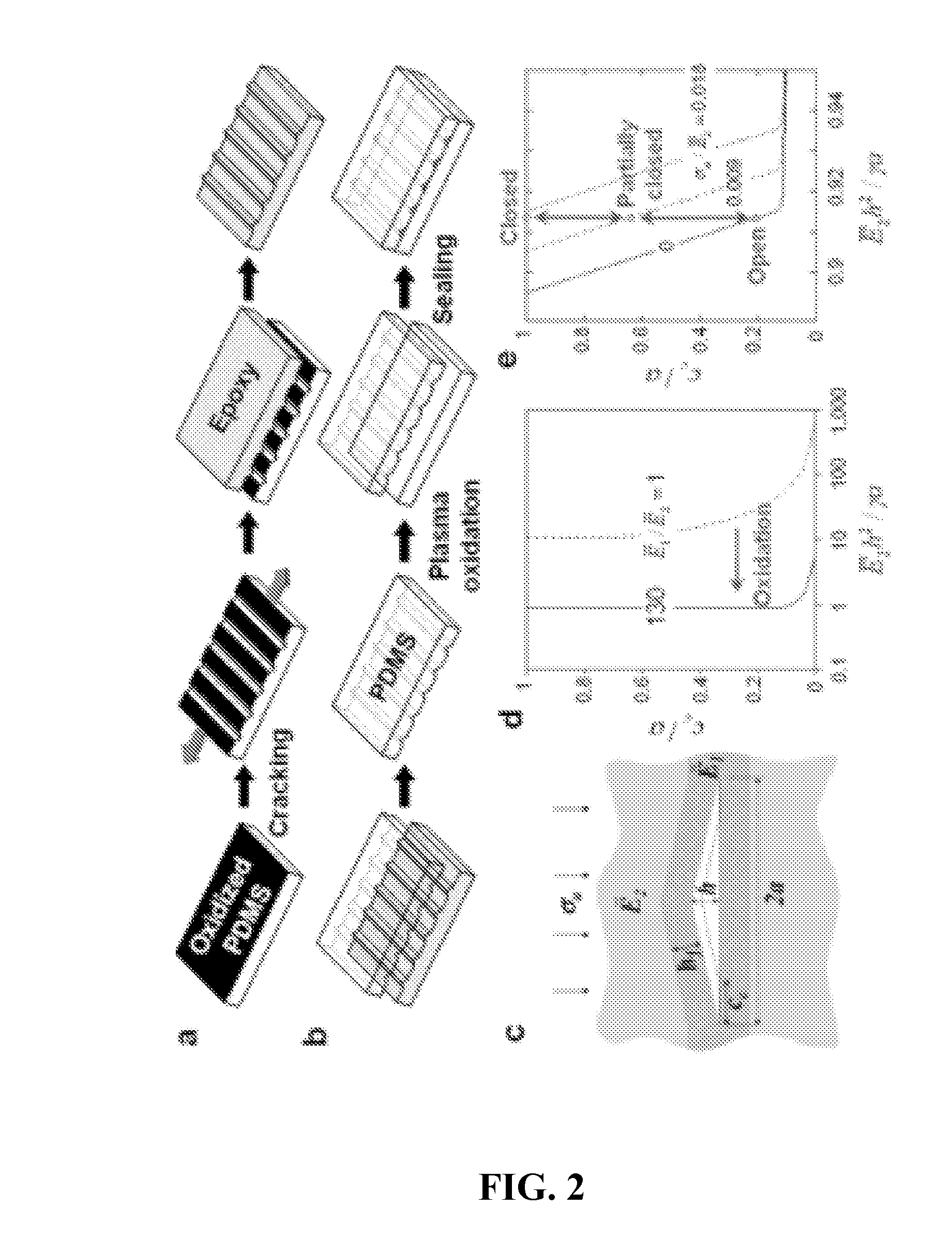
[0101]Generation of nanocrack patterns: PDMS (Sylgard 184, Dow Corning) base and curing agent were mixed at a weight ratio of 10:1. Degassed PDMS prepolymer was cast against a photolithographically-prepared SU8 (SU8-50, MicroChem Corp.) mold and cured at 60° C. for 4 hours to produce PDMS substrates with recessed inlet and outlet microchannel features. The substrates were then cleaned with adhesive tape and treated with oxygen plasma for 4 minutes in a bench-top plasma etcher (Plasma Prep II, SPI Supplies). Vacuum pressure and operation current used for plasma treatment were 150 mTorr and 30 mA, respectively. Subsequently, the oxidized PDMS surface was stretched to a strain of 5˜10% for 10 seconds by an electronically controlled stretcher (ST140, STREX Inc.) to create nanocracks.

[0102]Fabrication of nanochannel molds: The PDMS surface with nanocracks was silanized with (tridecafluoro-1,1,2,2-tetrahydrooctyl)-1-trichlorosilane for 1.5 hours in a vacuum desiccator. Nanochannel ...

example 2

Nano-Cracking of the Surface-Modified Layer of Poly(Dimethylsiloxane) Created by Exposure to Plasma Oxygen

[0112]This example describes an investigation of the material properties of plasma-oxidized PDMS. The properties of the PDMS are straightforward to determine with established experimental methods, and are presented in Section 2. Addressing the challenge of assessing the material properties of the surface-modified layer, Section 3 demonstrates a two-step method, using the AFM, to determine its thickness and elastic modulus. Finally, in Section 4 the fracture behavior of a surface-modified layer is discussed in the light of the measured material properties.

[0113]2 Materials Preparation and Properties of the Bulk PDMS

[0114]2.1 Materials Preparation

[0115]Initial studies showed that both the ratio of the polymer to the curing agent, and the curing schedule affected the constitutive behavior of the resulting elastomer. Therefore, care was taken to ensure that all experiments were perf...

example 3

Dynamic Modulation of Focal Adhesion Complexes in Response to Strain and Compression of Protein-Matrices

[0158]This example describes the growth of cells on protein coated cracks. FIG. 36 shows a schematic Illustration of cracking protocol layered system with PDMS substrate (thickness=3.5 mm)+Cr intermediate layer (10 nm thickness)+Au layer (40 nm thick) fastened to silanized glass slide with a thin layer of spin-coated PDMS through the sputtering / evaporation process to minimize external stresses. The system is removed from the glass slide by ethanol coating and fastened into stretching device. The entire surface of the system is coated with self-assembled monolayers (SAMs) of alkanethiolates with a terminally substituted oligo(ethylene glycol) group to make the Au surface non-fouling Strain is applied, the thin surface layers crack into the PDMS layer, revealing new PDMS substrate. The entire system is then coated with laminin / fibronectin—however, the adhesion protein selectively ad...


PUM

PropertyMeasurementUnit
Biological propertiesaaaaaaaaaa
Transport propertiesaaaaaaaaaa
Strain pointaaaaaaaaaa

Abstract

The invention relates to tunable elastomeric nanochannels for nanofluidic manipulation. In particular, the present invention relates to nanochannels for performing biological assays.

Description

[0001]This invention was made with government support under grant number EB003793 awarded by the National Institutes of Health and grant number DMI0403603 awarded by the National Science Foundation. The Government has certain rights in the invention.FIELD OF THE INVENTION[0002]The invention relates to tunable elastomeric nanochannels for nanofluidic manipulation. In particular, the present invention relates to nanochannels for performing biological assays.BACKGROUND OF THE INVENTION[0003]The success and proliferation of microfluidics research has spawned significant interest in nanofluidics research as techniques for nanofabrication are advanced and becoming more widespread. Nanofluidics research encompasses a very broad range of topics from chemistry to biology to physics; the promise of answers to fundamental questions in each is the goal. Some of the research being pursued includes the fundamental properties of liquids and the separation or sorting of molecules based on size and ...

Claims


Application Information

Patent Timeline
IPC IPC(8): G01N33/48C12M1/34C08F6/28C12M3/00C12Q1/68G01N33/543C12N5/00B29C55/00
CPCB01L3/502707B01L3/502761B01L2200/0663B01L2200/0668B01L2300/0864B82Y30/00B01L2300/123B01L2400/0418B01L2400/0487B01L2400/082B01L2300/0896
Inventor TAKAYAMA, SHUICHITHOULESS, MICHAELHUH, DONGEUNMILLS, KRISTEN L.DOUVILLE, NICHOLAS JOSEPH
Owner RGT UNIV OF MICHIGAN
Why Eureka
Try Eureka