Switchboard bus assembly in which material requirements are reduced without reducing performance

a technology of switchboard and bus, which is applied in the field of switchboard bus, can solve the problems of poor thermal dissipation and current distribution, increased cost of expensive copper, and increased current density near the surface of the conductor

Active Publication Date: 2010-07-01
SCHNEIDER ELECTRIC USA INC
View PDF10 Cites 9 Cited by
  • Summary
  • Abstract
  • Description
  • Claims
  • Application Information

AI Technical Summary

Problems solved by technology

As the length of these conductors increases, the temperature of the surrounding air due to natural convection increases, resulting in poor thermal dissipation and current distribution.
In the case of flat conductors, to counteract the adverse thermal effects, additional flat conductors are stacked together, but at the cost of an increase in the amount of expensive copper.
A related problem is a phenomenon called the “skin effect,” which holds that the current density near the surface of the conductor is greater than at its core.
Because of increased conductor volume, laminated flat conductors exhibit relatively poor current distribution due to the skin effect.
Moreover, in multi-phase systems, adjacent conductors of different phases are subjected to another undesirable phenomenon called the “proximity effect,” which relates to how current flowing through one phase interferes with current flowing through an adjacent phase.
As a result, some portions of conductors of one phase can get hotter than other portions of the same or different conductor in the same phase, resulting in uneven current distribution within the conductors composing a conducting phase.
Proximity effects relate to the undesired tendency of current to favor the conductor surface proximate an adjacent phase conductor, resulting in uneven current distribution within the phase conductor and uneven heating of the conductors.

Method used


Image

  • Switchboard bus assembly in which material requirements are reduced without reducing performance
  • Switchboard bus assembly in which material requirements are reduced without reducing performance
  • Switchboard bus assembly in which material requirements are reduced without reducing performance

Examples


Embodiment Construction

[0015]Although the invention will be described in connection with certain aspects and / or embodiments, it will be understood that the invention is not limited to those particular aspects and / or embodiments. On the contrary, the invention is intended to cover all alternatives, modifications, and equivalent arrangements as may be included within the spirit and scope of the invention as defined by the appended claims.

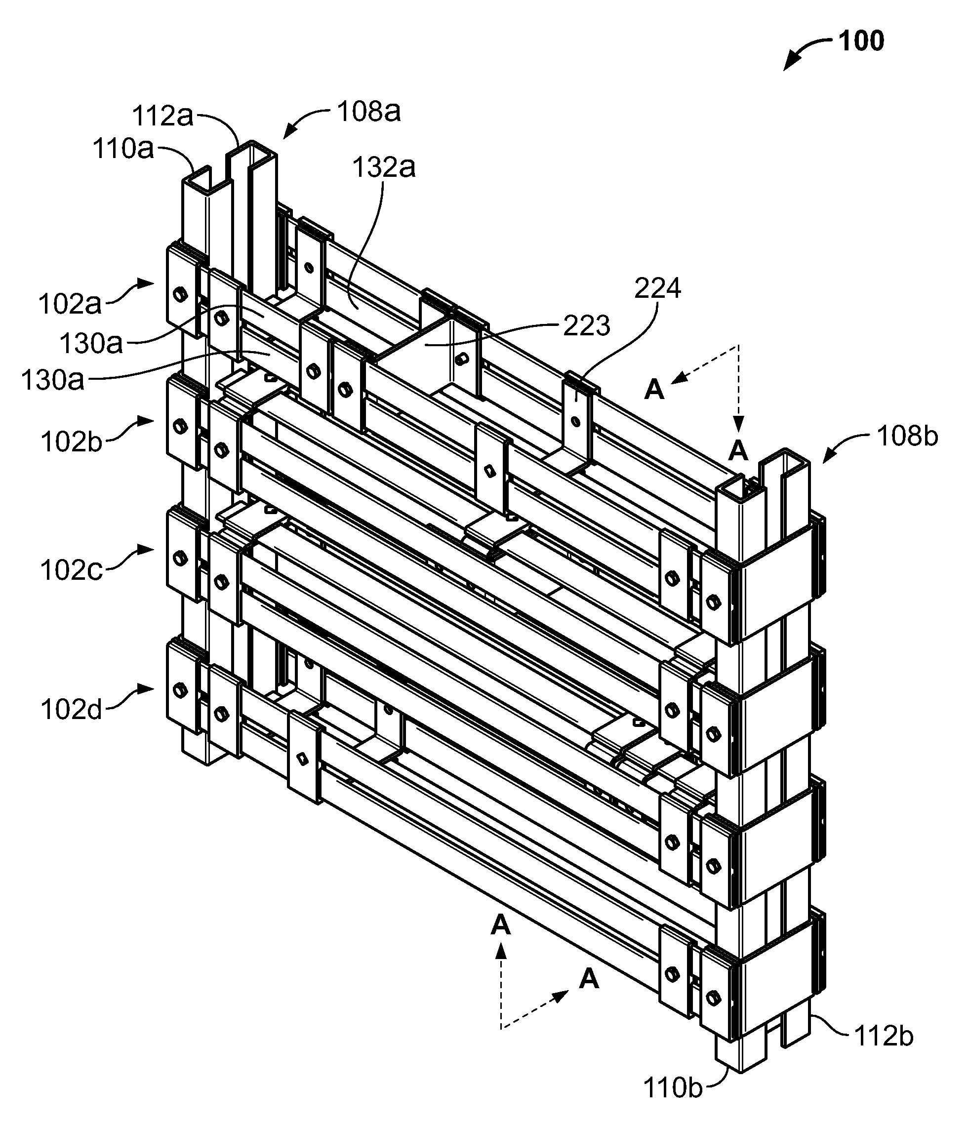
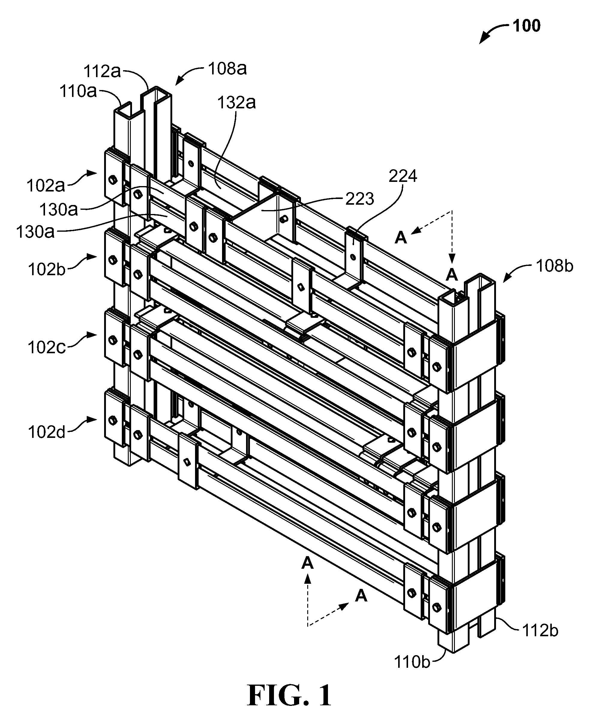
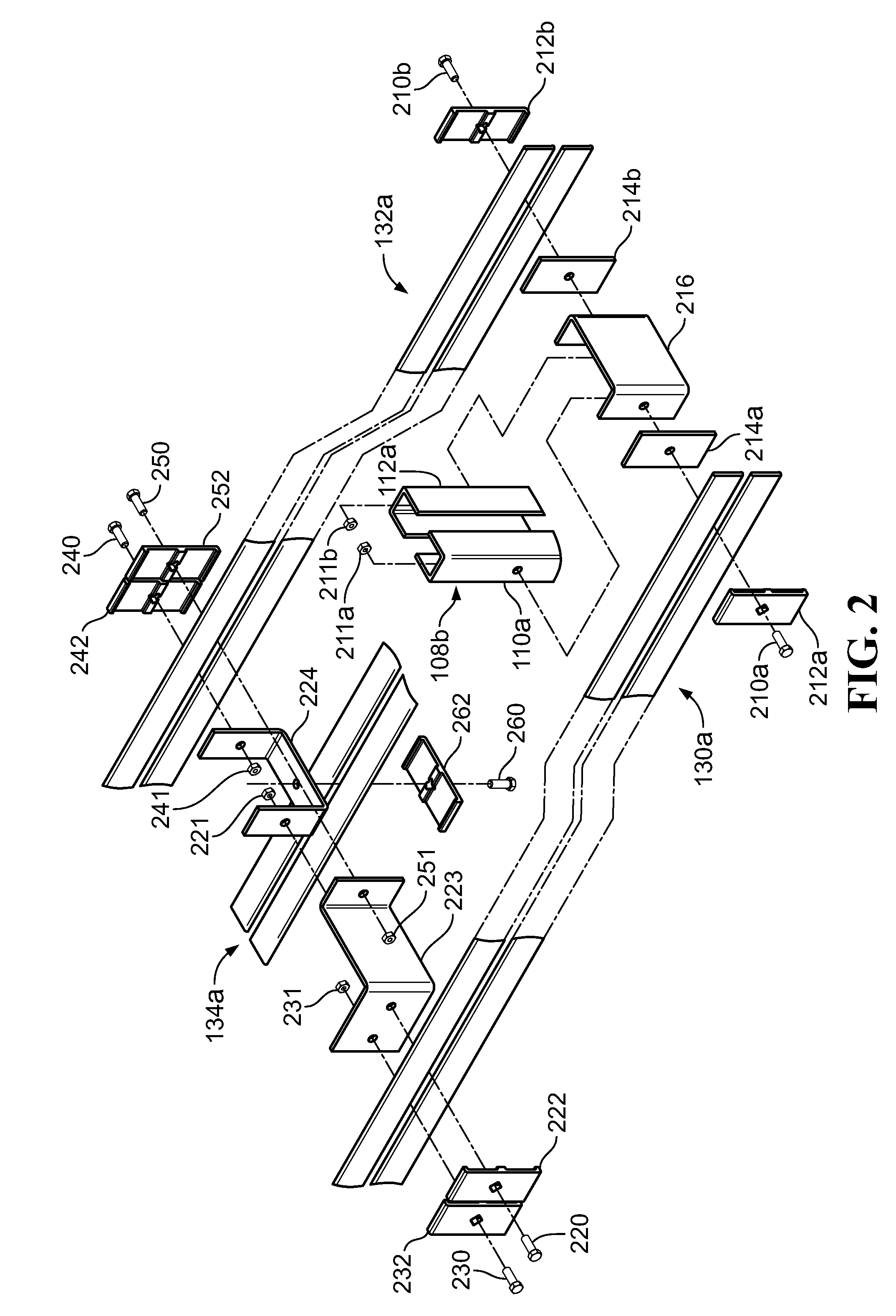
[0016]An isometric view of a bus system 100 for use in electrical distribution equipment such as switchgear, switchboards, and motor control centers, is shown inFIG. 1. FIG. 2 shows a portion of the bus system 100 in exploded view. In an exemplary embodiment, the bus system 100 includes three horizontal phase conductors or buses 102a,b,c, one for each phase of a polyphase alternating current distributed by the electrical distribution equipment (not shown). The bus system 100 further includes a bus 102d corresponding to a neutral conductor. The buses 102 are made of a conduc...


PUM


Abstract

A bus system for use in electrical distribution equipment includes a generally U-shaped arrangement of conductor conductors for supplying very high amperage (e.g., above 2000 amps) alternating current to the electrical distribution system. Compared to prior-art conductor arrangements, using the present arrangement, the conductor conductors of a phase can be fabricated from less copper, which is an expensive metal. They also achieve better thermal dissipation and current distribution and mitigate skin effects. As a result, resistive losses, which increase with increased temperature, are reduced.

Description

FIELD OF THE INVENTION[0001]The present invention relates generally to bus systems, and in particular, to switchgear bus systems for electrical power distribution.BACKGROUND OF THE INVENTION[0002]Electrical distribution equipment, including switchboards, switchgear, and motor control centers, use conductors to connect circuit breakers and other protection equipment to loads. Existing conductors include one or more flat conductors depending upon the desired current rating or ampacity of the distribution equipment. As the length of these conductors increases, the temperature of the surrounding air due to natural convection increases, resulting in poor thermal dissipation and current distribution. In the case of flat conductors, to counteract the adverse thermal effects, additional flat conductors are stacked together, but at the cost of an increase in the amount of expensive copper. For example, a cross-sectional view of a portion of a known bus system is shown in FIG. 5A. Four lamina...

Claims


Application Information

Patent Timeline
Patent Type & Authority Applications(United States)
IPC IPC(8): H02G5/00
CPCH02B1/21
Inventor DIAZ, MAURICIOISLAS, LUIS
Owner SCHNEIDER ELECTRIC USA INC
Why Eureka
Try Eureka