System and method for sealing in a conduit a space between an inner wall of the conduit and at least one pipe or cable extending through the conduit

a technology of pipe or cable and inner wall, which is applied in the direction of fluid pressure sealing joints, pipe elements, pipe supports, etc., can solve the problems of unwelcome intrusion of heat through material, inability to install insulating lining, and inability to meet the needs of penetration, so as to enhance the stability of the support structure, the effect of further stability of the sealant layer and high frictional for

Active Publication Date: 2010-07-01
BEELE ENG
View PDF13 Cites 19 Cited by
  • Summary
  • Abstract
  • Description
  • Claims
  • Application Information

AI Technical Summary

Benefits of technology

[0017]In an embodiment, the rubber element is a longitudinal element. A longitudinal rubber element is very easily placed in the conduit and allows for an easy way of building up the support structure. After all, the longitudinal element can be placed parallel to the pipe extending through the conduit. By stacking such longitudinal elements all oriented along the pipe, a support structure is conveniently obtained in the conduit. By adding more and more of these elements into the conduit, which is not too difficult given the structure already formed and the shape of the additional elements, the structure will be clamped in the conduit.
[0018]In an embodiment, the longitudinal rubber element is a tubular element, or a number of the longitudinal elements can together form at least one tubular element. The tubularity of such elements offers the advantage that the sealing system will be lighter, and that the elements can be deformed in a transverse direction. It allows for a firm clamping of the elements in the conduit, further enhancing the stability of the support structure, leading to further stability of the sealant layer. The parts of the rubber elements which are clamped against each other inhibit relative movement of these parts due to high normal and high frictional forces at the places of contact. This also applies to contact between rubber elements and the pipe or cable, or inner wall of the conduit. This all contributes to the “fixing” of the support structure in the conduit. The support structure can also provide support to the pipes or cables extending through the conduit. Another advantage of the tubular elements is that air will be entrapped in the tubular elements, providing in use optimal thermal insulation of the sealing system.
[0019]In an embodiment, the rubber has a hardness in a range of 70 to 78 Shore A, preferably about 74 Shore A. It has turned out that such a hardness provides rubber elements with very good mechanical properties, but still allowing for deformation of the rubber elements, and as such contributing to the formation of a stable support structure in the conduit.
[0020]In an embodiment, the mantle wall is closed in itself, i.e. non-split, preferably with a thickness of 2-5 mm, or even more, preferably 3-4 mm. This ensures stability of the shape of the rubber element.
[0021]In an embodiment, each element of the at least one rubber element and / or the sealant has a colour which contrasts to black. As will further be described during a description of preferred embodiments, the rubber elements are not consumed when exposed to a nearby fire. Although normally everything is blackened when exposed to a nearby fire, the rubber elements and the sealant, in particular at the unexposed side of the conduit, will not change colour during exposure of the conduit to a nearby fire, and as such quickly indicate the state of the sealing during and after a fire. This enables rapid understanding of the phenomena which took place during the fire. This will enhance further improving fire safety regulations aboard vessels and other offshore constructions.

Problems solved by technology

These penetrations are seen as unwelcome necessities in such a construction.
Such weak spots do not manifest themselves to a great extent in the mechanical strength of the construction but much more in the undesired transport of physical phenomena throughout the structure.
This is because entrance of heat through material of which the conduit is made, is often inhibited by a thermally insulating lining provided against the outer wall of the conduit and the construction element in which the conduit is incorporated.
However, nowadays, thermally insulating lining is not always applied around the conduit and consequently heat can be conducted through the conduit material from an outside to an inside side of the conduit.
When exposed to a nearby fire, the heat transferred into the conduit causes the expandable sleeves to expand and as such to seal off the conduit by forming a soft, almost powder-like mass without offering mechanical stability to the sealing.
The expansion may cause the sealant layer to break.
Consequently, the sleeves are rather soft.
In other words, due to the uncertainty in the amount of heat reaching the sealing system, the system is made very sensitive.
An “excess” of heat results consequently in an overresponding expansion, even outwards the conduit.

Method used


Image

  • System and method for sealing in a conduit a space between an inner wall of the conduit and at least one pipe or cable extending through the conduit
  • System and method for sealing in a conduit a space between an inner wall of the conduit and at least one pipe or cable extending through the conduit
  • System and method for sealing in a conduit a space between an inner wall of the conduit and at least one pipe or cable extending through the conduit

Examples


Embodiment Construction

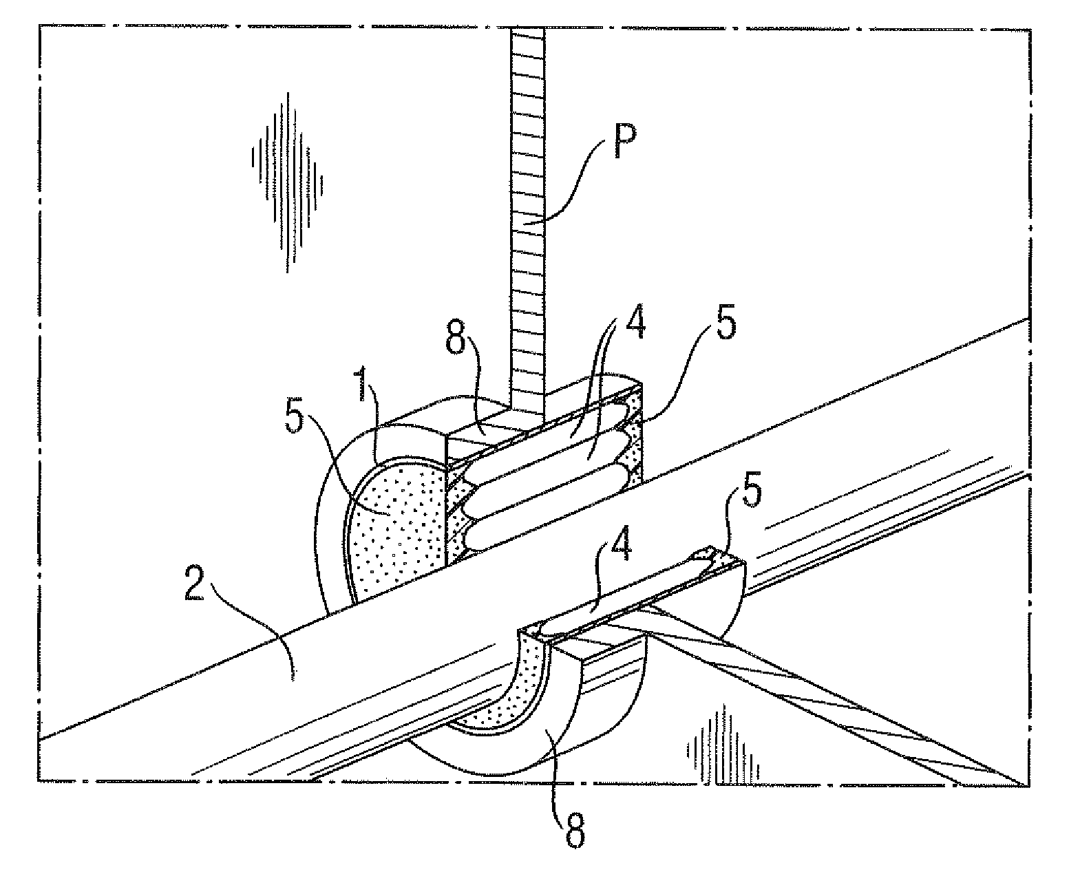
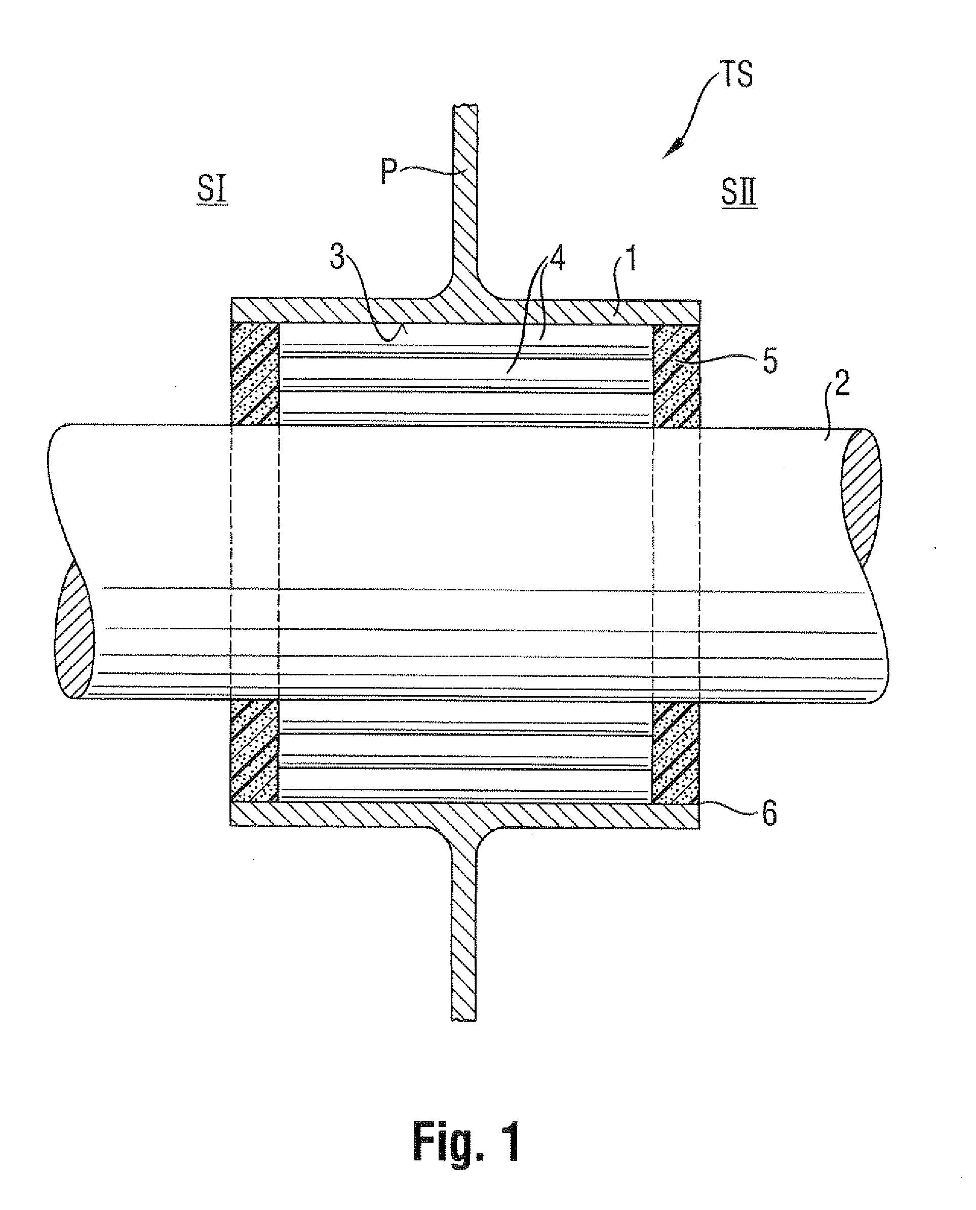
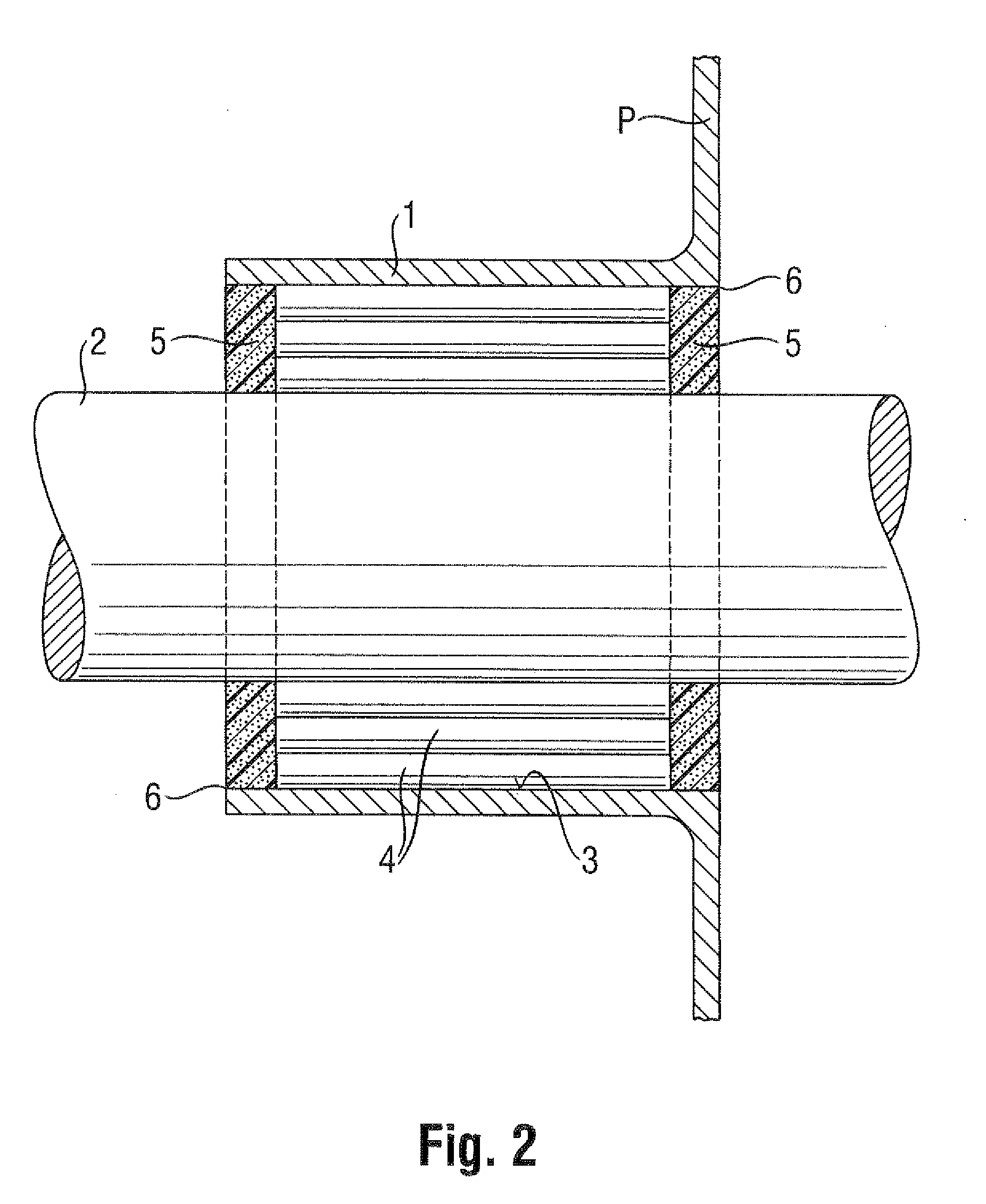
[0032]FIG. 1 shows schematically an example of a cross section of a transit system TS in which, as shown, a system according to the invention can be applied. The transit system TS is usually incorporated in a metal substantially plate-shaped construction element P. This plate-shaped construction element P can be situated between two spaces SI, SII, as separated by the construction element P. The plate-shaped construction element may for instance be a part of a bulkhead, a wall or a deck in or on a ship or another construction that is substantially constructed of a metal such as for instance steel. The transition system TS comprises a conduit 1, made of a material which is in this example thermally conductive. The conduit 1 may be welded into an opening of the construction element P. Although as shown in this example, the conduit 1 is incorporated in a metal substantially plate-shaped construction element P, it is also possible that the conduit 1 is incorporated in for instance a con...


PUM


Abstract

System for sealing in a conduit a space between an inner wall of the conduit and at least one pipe or cable extending through the conduit, wherein the system comprises: at least one rubber element for providing in the conduit a support-structure which is clampable between the inner wall and the at least one pipe or cable; and a sealant for application against the support-structure and for sealing off at least one end of the conduit between the inner wall and the at least one pipe or cable.

Description

INTRODUCTION[0001]The invention is related to a system and a method for sealing in a conduit a spade between an inner wall of the conduit and at least one pipe or cable extending through the conduit.THE BACKGROUND OF THE INVENTION[0002]A sealing system is usually applied in a conduit which is itself incorporated in a construction element that divides, for instance, two compartments. A pipe or cable may extend through the conduit from one of the two compartments into the other. Such a conduit is often present on board of vessels and / or other offshore applications such as oil rigs. These conduits are often referred to as pipe or cable penetrations or transit systems. These penetrations are seen as unwelcome necessities in such a construction. Pipes for, for instance, water distribution and water wastage systems, air conditioning systems, hydraulic and pneumatic control, sprinkler etc. but also for transport of gas, or oil, need to be extending throughout such a construction, even thou...

Claims


Application Information

Patent Timeline
Patent Type & Authority Applications(United States)
IPC IPC(8): F16L5/02
CPCF16L5/04H02G3/22H02G3/0412F16L7/02F16L55/00F16L57/00
Inventor BEELE, JOHANNES ALFRED
Owner BEELE ENG
Why Eureka
Try Eureka