Adaptive angle and power adaptation in 3d-micro-mirror lidar

a technology of micromirror and adaptive angle, applied in the field of adaptive angle and power adaptation in 3d micromirror lidar, can solve the problems of insufficient spatial resolution of images and the increase in signal-to-noise ratio, and achieve the effects of reducing radiation power, reducing deflection angle, and improving detection of objects

Active Publication Date: 2010-07-01
ROBERT BOSCH GMBH
View PDF7 Cites 97 Cited by
  • Summary
  • Abstract
  • Description
  • Claims
  • Application Information

AI Technical Summary

Benefits of technology

[0013]The detection of objects is able to be improved by making the radiation power of the laser beam selectable as a function of the frequency and/or the amplitude of the control signal of the micromechanical mirror. When the deflection angle is reduced, this may require a reduction of the radiation power for a detection in the near field. On the other hand, a detection in the distant field may be improved by reducing the deflection angle of the micromechanical mirror and additionally increasing the radiation power of the laser radiation.
[0014]A LIDAR (light detection and ranging) system for detecting the environment of a vehicle and for driver assistance is able to be improved with regard to its suitability for detecting objects both in the near range and the distant range in that the detection field is specified in the vertical and horizontal direction via an adaptation of the amplitude of oscillation of the micromechanical mirror. Driver-assistance systems evaluate a region in front of the vehicle having twice the width of the roadway, for example. This requires a larger angular range of the LIDAR in the near range than for the distant range. By making the angular range adjustable, the system can be rapidly adapted to the individual measuring task, also temporarily while driving.
[0015]Adapting the detection field to a measuring task may be achieved in example embodiments of the present invention, with respect to a method, by specifying the frequency and/or the amplitude of a control signal of the micromechanical mirror. This makes it possible to adapt the object detection to the measuring task in the near field and in the distant field, so that the system is suitable both for a parking function and for a distance LIDAR, for example. An increase in the angular resolution is achieved by reducing the amplitude of oscillation of the micromechanical mirror. This makes it possible to analyze small objects or objects in th

Problems solved by technology

In that case, the image frequently has insufficient spatial resolution because the system is operating at a constant angular resolution.
A

Method used


Image

  • Adaptive angle and power adaptation in 3d-micro-mirror lidar
  • Adaptive angle and power adaptation in 3d-micro-mirror lidar
  • Adaptive angle and power adaptation in 3d-micro-mirror lidar

Examples


Embodiment Construction

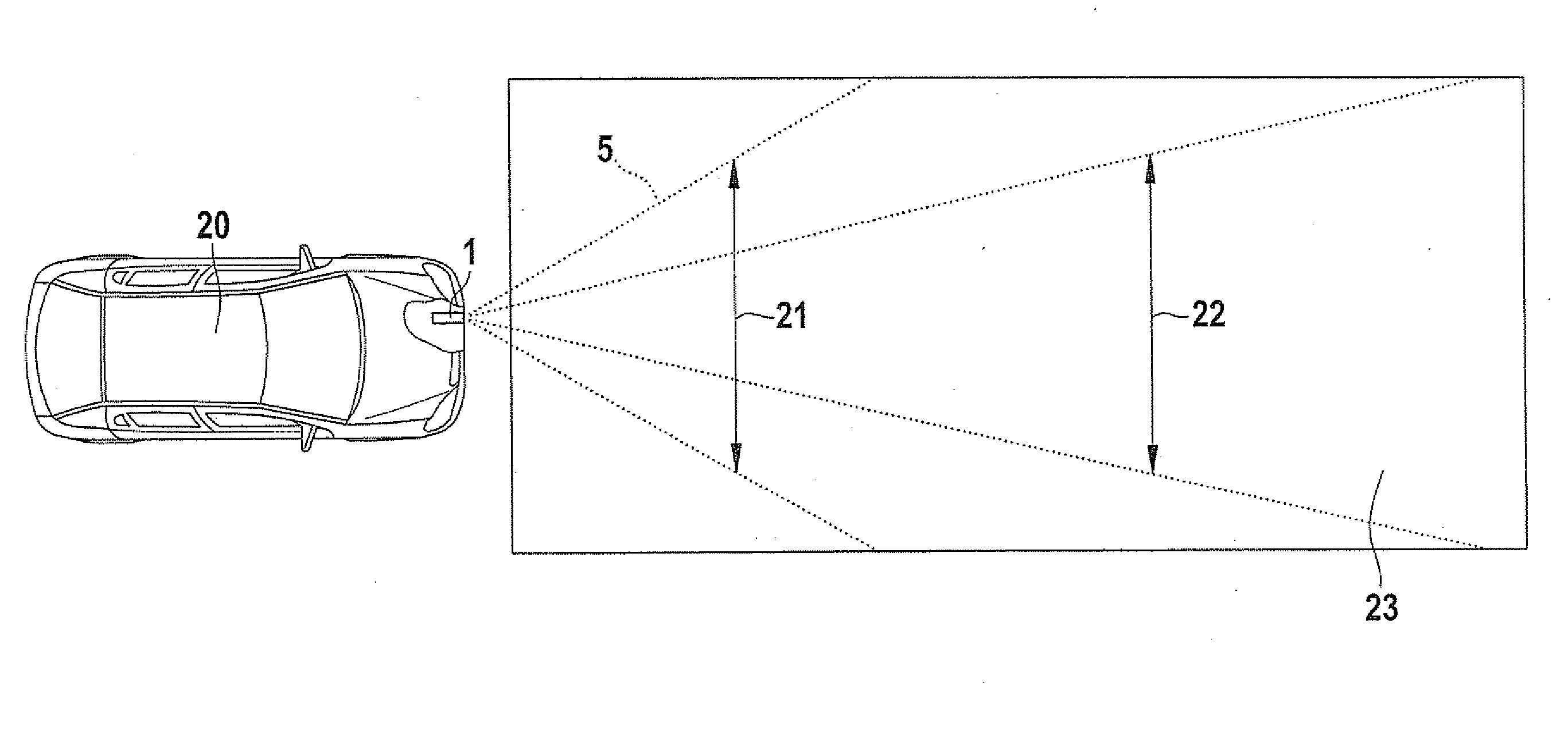
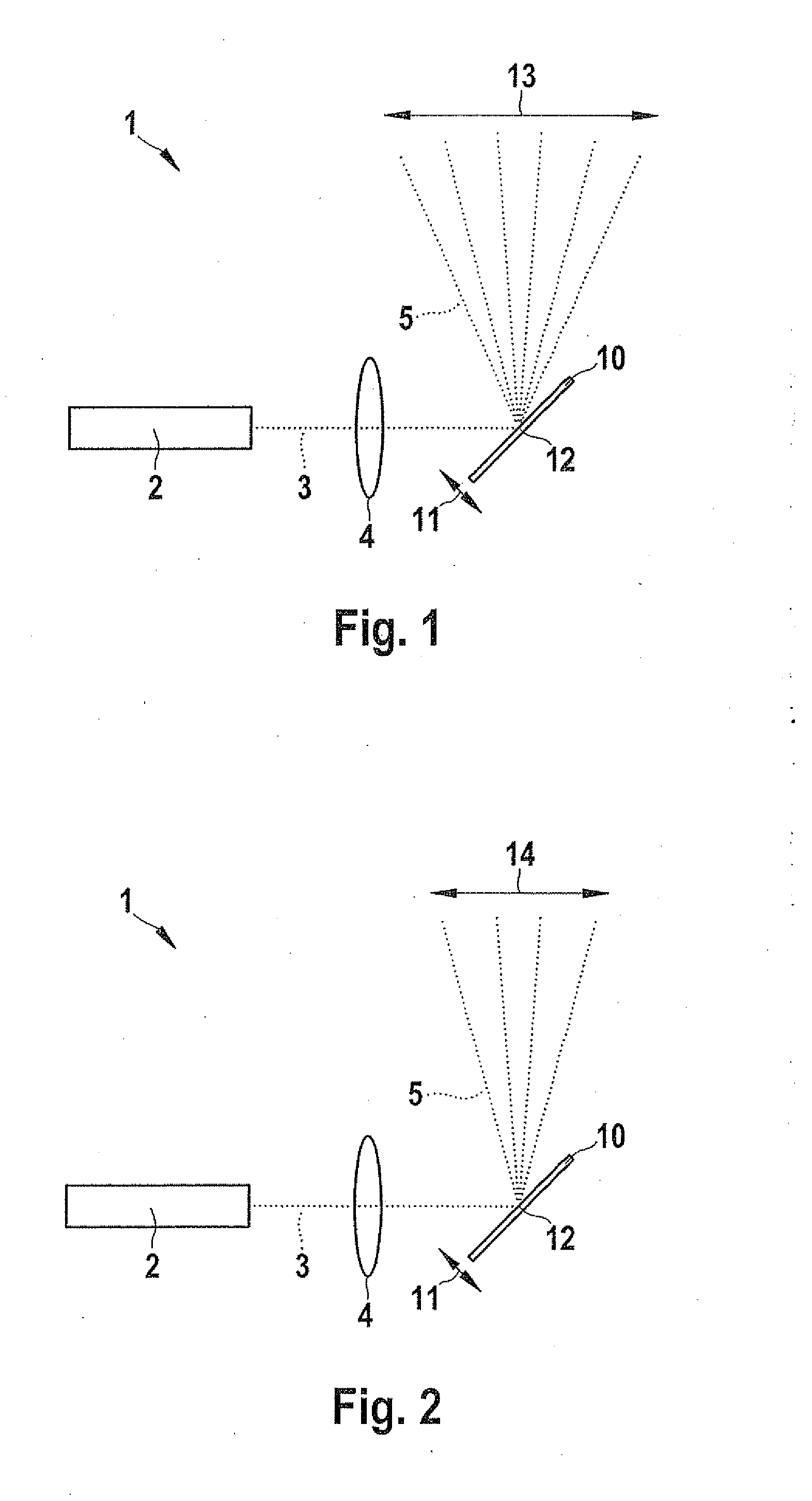
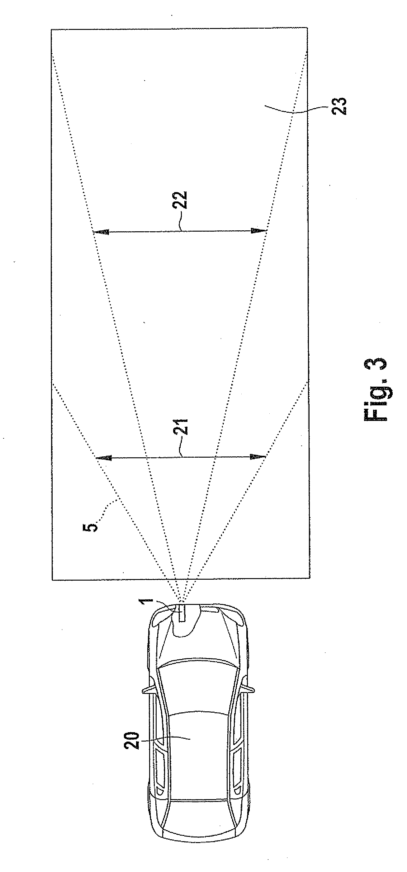
[0023]FIG. 1 schematically illustrates a LIDAR system 1 for recording the geometry of the environment of a motor vehicle. Using a laser 2, a laser beam 3 is produced, which is shaped via a focusing lens 4 and forwarded to a micromechanical mirror 10. Micromechanical mirror 10 is rotatable about an axis of rotation 12 situated perpendicular to the drawing plane, so that its circumference is able to execute a periodic mirror motion 11. Micromechanical mirror 10 may be driven electrostatically or electromagnetically. When controlled at its resonance frequency by a specified control signal, it executes an oscillating mirror motion 11, so that a scanning beam 5, which is formed by laser beam 3 reflected at micromechanical mirror 10, sweeps a first scanning region 13.

[0024]FIG. 2 shows the LIDAR system 1 of FIG. 1 when controlled at a frequency that deviates from the resonance frequency, or by a control signal having a reduced amplitude. Laser beam 3 emitted by laser 2 is shaped by focusi...


PUM


Abstract

A device for recording a geometry of an environment of a device in a detection field with the aid of laser scanning may include a laser beam controlled by an oscillating micromechanical mirror. The detection field is specifiable in the vertical and horizontal directions by adapting an amplitude of oscillation of the micromechanical mirror. Driver-assistance systems are used for tasks both in the near field, such as a parking function, and in the distant field of the vehicle, such as a distance control or the detection of obstacles on the roadway. If the amplitude of the oscillation of the micro-mirror is then reduced in the horizontal direction and/or vertical direction, the spatial resolution for the reduced detection range is improved. Moreover, the higher intensity of the laser radiation impinging on the smaller detection region improves the signal-to-noise ratio of the detected signal.

Description

FIELD OF THE INVENTION[0001]The present invention relates to a device for recording a geometry of an environment of a device in a detection field with the aid of laser scanning using a laser beam controlled by an oscillating micromechanical mirror. The present invention further relates to a method for recording a geometry of an environment in a detection field by laser scanning with the aid of a laser beam controlled by an oscillating micromechanical mirror, the device determining a contour of the environment from the intensity, specified by a receiver, of the laser radiation backscattered or reflected from the environment, and the device determining the distance of objects in the environment from the propagation time of laser pulses.BACKGROUND INFORMATION[0002]To produce an image of an environment of a vehicle for a driver-assistance system, a system based on LIDAR (light detection and ranging) may be used in addition to other systems. In a LIDAR system, the environment is illumina...

Claims


Application Information

Patent Timeline
IPC IPC(8): G01C3/08G08G1/16
CPCG01S17/42G01S17/936G01S7/4817G01S17/931
Inventor FIESS, REINHOLDSTEINKOGLER, SASCHA
Owner ROBERT BOSCH GMBH
Why Eureka
Try Eureka