Adiabatic tapered composite waveguide for athermalization

a composite waveguide and athermalization technology, applied in the field of integrated optics, can solve the problems of not being compatible with optical integration, deterioration of optical properties, and affecting the quality of optical components, so as to reduce temperature dependence, reduce temperature dependence, and avoid optical loss

Inactive Publication Date: 2010-07-01
CYOPTICS ISRAEL
View PDF6 Cites 8 Cited by
  • Summary
  • Abstract
  • Description
  • Claims
  • Application Information

AI Technical Summary

Benefits of technology

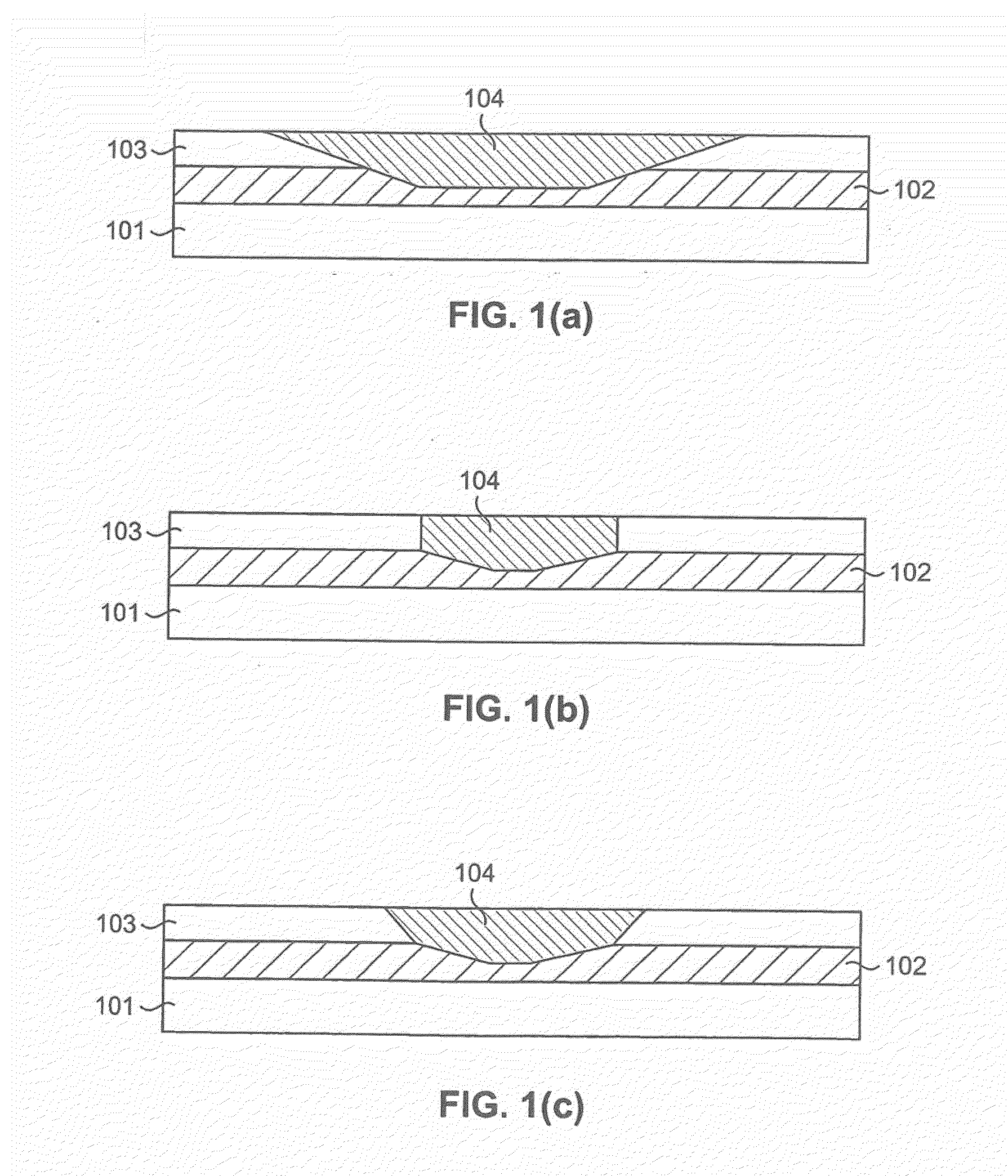
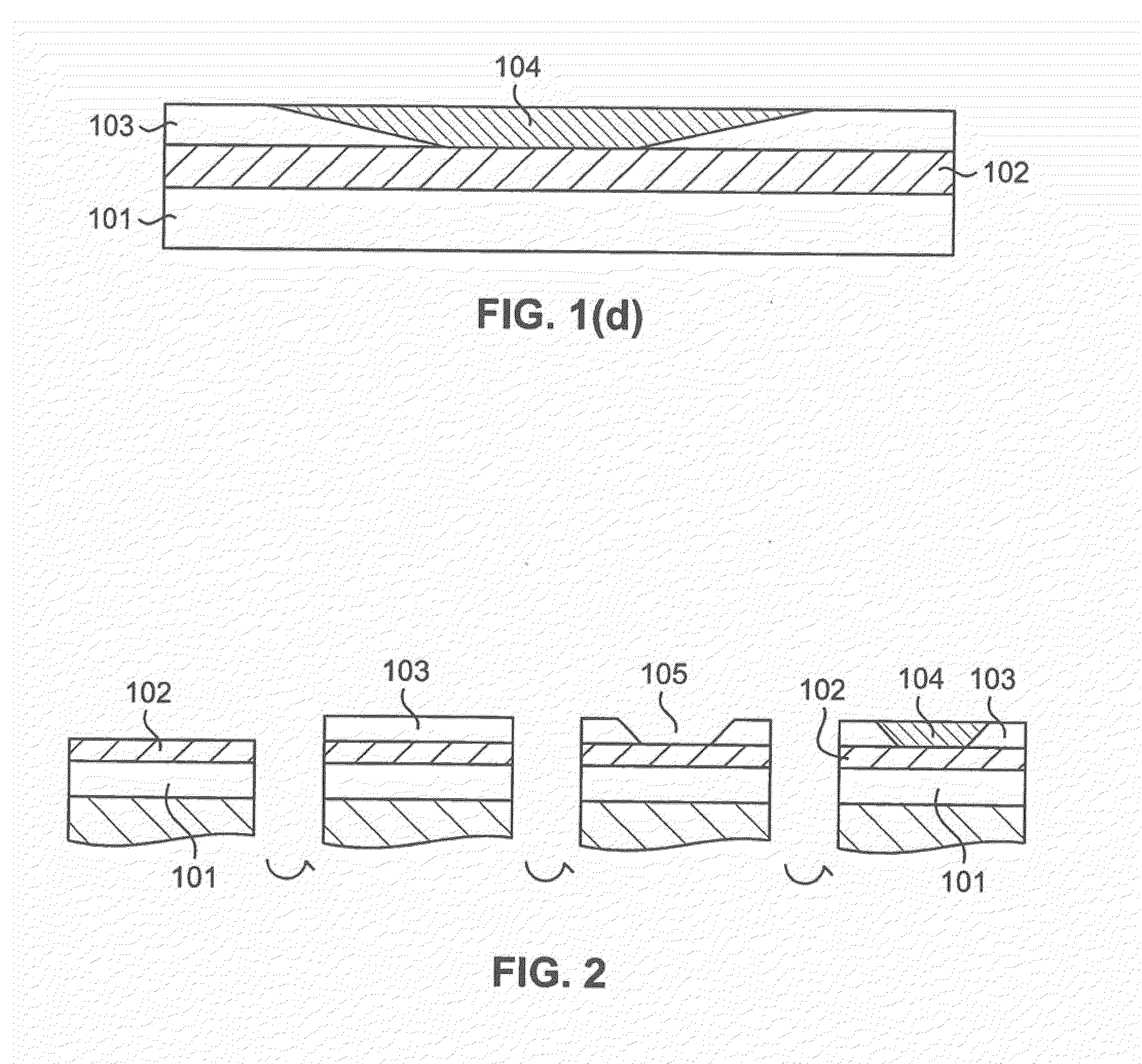
[0005]The present invention discloses a method of PLC filter athermalization, which combines the advantages of the two latter approaches. In a tapered composite waveguide circuit only a small portion of a PLC circuit is made hybrid, i.e. composed of silica-based core material and another material with negative thermo-optic coefficient. The region between the regular PLC and hybrid PLC sections is adiabatically tapered, so that there is no optical loss between the two sections. The thermo-optic coefficient of the hybrid waveguide is designed in such a way as to be equal and opposite in sign to the ds / dT coefficient of the regular waveguide. Thus the thermally induced spectral shift of the filter built on this principle can be made negligibly small.
[0006]In one particular embodiment of the invention, a planar waveguide circuit is provided that includes a silica-based planar optical waveguide circuit having a lower cladding, a core and an upper cladding. At least one input waveguide and one output waveguide are each coupled to the optical waveguide circuit. At least one adiabatic tapered waveguide section is located in the waveguide circuit, which has an upper cladding segment that tapers down to at least the core to define a tapered recess. A filler material having a negative thermo-optic coefficient fills the tapered recess so that the optical waveguide circuit has an optical characteristic with a reduced temperature dependence.

Problems solved by technology

Such devices, even when providing good performance at constant temperature, often deteriorate rapidly when subjected to thermal variations such as fluctuations in ambient temperature.
For a transmission peak in a passband filter centered at about 1550 nm, this value translates to shift of about 0.8 nm (or equivalently about 100 GHz) when temperature changes between 0 and 80° C. This shift corresponds to one spacing between typical DWDM channels and is therefore completely unacceptable.
These solutions, however, are typically bulky and often not compatible with optical integration.
However, this method typically suffers from excess radiation loss in the groove region.
This solution, while it offers distinct advantages over the two previous ones, is often not manufacturable or compatible with other PLC elements.
This is largely due to the polymer upper cladding, which limits processing conditions in wafer manufacturing, limits design options in waveguide optimization, hinders device reliability and complicates chip attachment procedures during packaging.

Method used


Image

  • Adiabatic tapered composite waveguide for athermalization
  • Adiabatic tapered composite waveguide for athermalization
  • Adiabatic tapered composite waveguide for athermalization

Examples


example 1

[0026]FIGS. 6(A)-6(C) each show an examples of arrayed waveguide gratings (AWG) with composite waveguides (top views) in accordance with the present invention. The AWG includes first and second free propagating optical coupling regions that are coupled by an arrayed waveguide region that includes a plurality of optical paths optically coupling the first coupling region to the second coupling region. This AWG could serve as an athermal wavelength multiplexing or de-multiplexing filter. The inventive athermalization method could be applied to any AWG design. The shape and size of the tapered region should be matched to the shape and size of a particular AWG, e.g. ΔL″ should be matched to the FSR of a given grating according to equations 4 and 5. FIG. 6A shows a tapered section 501 in the arrayed waveguide region of the AWG. In this instance the length of the composite section in each of the grating waveguide is given by

ΔL″i=ΔL*i  (6)

[0027]FIG. 6B shows a tapered section 502 located in...

example 2

[0028]FIG. 7 shows a single stage Mach-Zehnder interferometer (MZI) filter made athermal using the composite waveguide approach of the present invention. As shown, the tapered section is positioned in the longer arm of the MZI. It length is chosen to satisfy equation 5, where L is given by the MZI arm length difference. More complex multistage filters using multiple MZIs can be made athermal using the same approach.

example 3

[0029]FIG. 8 shows an etalon filter based on a ring resonator circuit that is athermalized in accordance with the present invention. In this case L is the length of the ring resonator. More complex filters with multiple rings can be made athermal using the same approach. Furthermore, all pass filters with tunable or fixed chromatic dispersion compensation can be made athermal using the same approach.


PUM


Abstract

A planar waveguide circuit includes a silica-based planar optical waveguide circuit having a lower cladding, a core and an upper cladding. At least one input waveguide and one output waveguide are each coupled to the optical waveguide circuit. At least one tapered waveguide section is located in the waveguide circuit, which has an upper cladding segment that tapers down to at least the core to define a tapered recess. A filler material having a negative thermo-optic coefficient fills the tapered recess so that the optical waveguide circuit has an optical characteristic with a reduced temperature dependence.

Description

STATEMENT OF RELATED APPLICATIONS[0001]This is a continuation-in-part of U.S. patent application Ser. No. 11 / 522,853, filed Sep. 18, 2006, entitled “Tapered Composite Waveguide For Athermalization”, which is incorporated by reference in its entirety herein.FIELD OF THE INVENTION[0002]The present invention relates to the field of integrated optics and particularly to the production of wavelength filtering devices whose essential optical characteristics do not depend on fluctuations in ambient temperature.BACKGROUND OF THE INVENTION[0003]Integrated optical waveguide circuits combine miniaturized waveguides and optical devices into a functional optical system incorporated onto a planar substrate. These planar lightguide circuits (PLCs) can incorporate a multitude of devices many of which depend on filtering, or the ability to select and perform specific operations upon individual channels of a dense-wavelength-division-multiplexed (DWDM) optical system. Such devices, even when providin...

Claims


Application Information

Patent Timeline
Patent Type & Authority Applications(United States)
IPC IPC(8): G01B9/02G02B6/10G02B6/26
CPCG02B6/12011G02B6/12014G02B6/12028G02B6/1228G02B2006/12107G02B2006/12159
Inventor FROLOV, SERGEY
Owner CYOPTICS ISRAEL
Why Eureka
Try Eureka