Instrument with microfluidic chip

a microfluidic chip and instrument technology, applied in the direction of engine diaphragms, laboratory glassware, diaphragm valves, etc., can solve the problems of incompatibility between microfluidic devices and existing upstream purification and downstream analytical devices

Active Publication Date: 2010-07-01
INTEGENX
View PDF101 Cites 136 Cited by
  • Summary
  • Abstract
  • Description
  • Claims
  • Application Information

AI Technical Summary

Benefits of technology

[0019]Another aspect of the invention provides for a method for mixing a first liquid and a second liquid comprising positioning a first bolus of the first liquid adjacent and downstream of a second bolus of the second liquid within a channel, positioning a third bolus of a third liquid adjacent and upstream of the second bolus of the second liquid within a channel, moving the first bolus, the second bolus,

Problems solved by technology

In the absence of standards controlling external dimensional form factors, the nature of the upstream and downstream external interface, and the length, cross-sectional geometry, and diameter of the internal microfluidic pathways, such microfluidic devices often proved incompatible with one another and with existing

Method used


Image

  • Instrument with microfluidic chip
  • Instrument with microfluidic chip
  • Instrument with microfluidic chip

Examples


Embodiment Construction

I. Microfluidic Chip Device

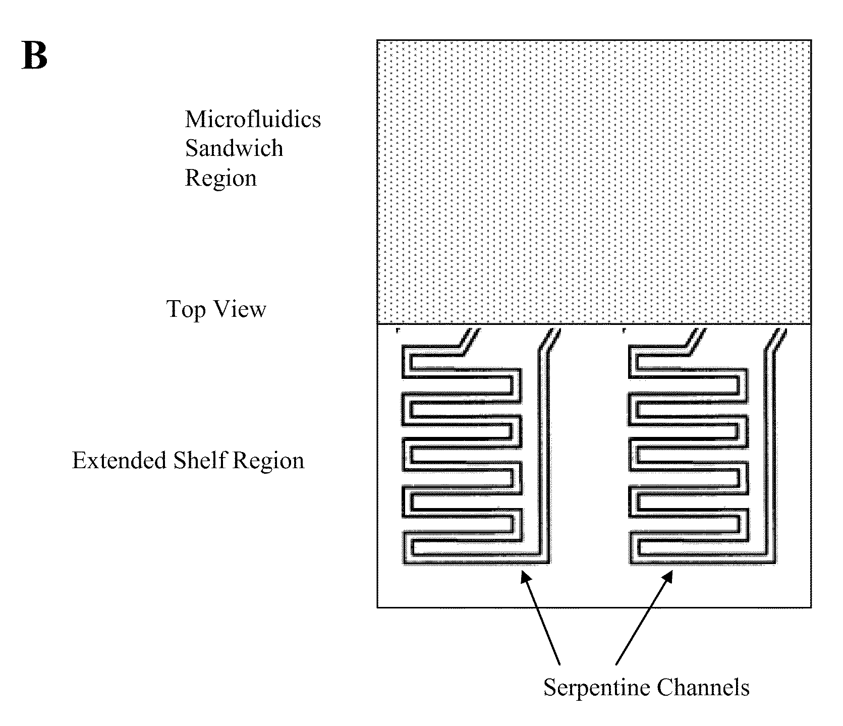
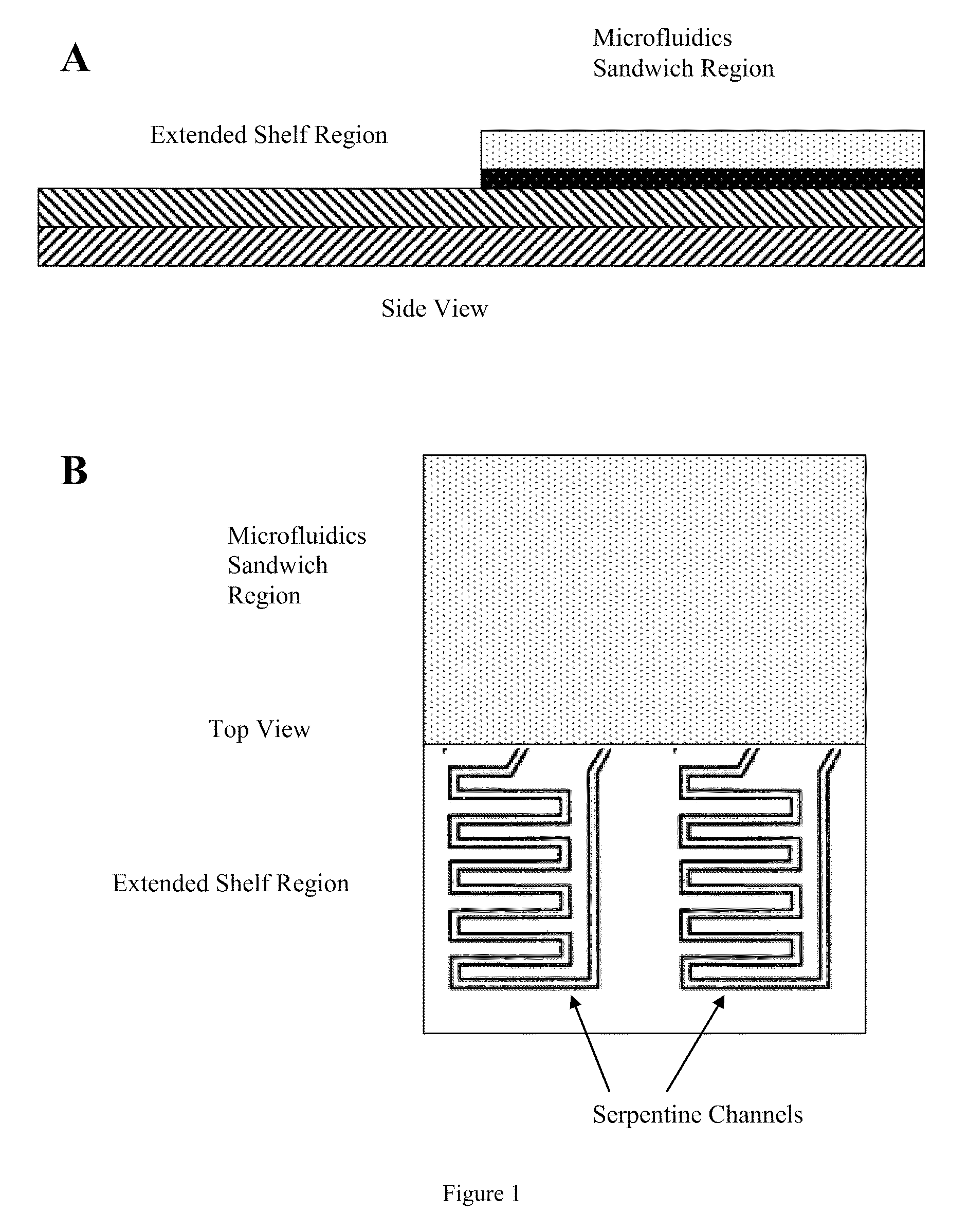
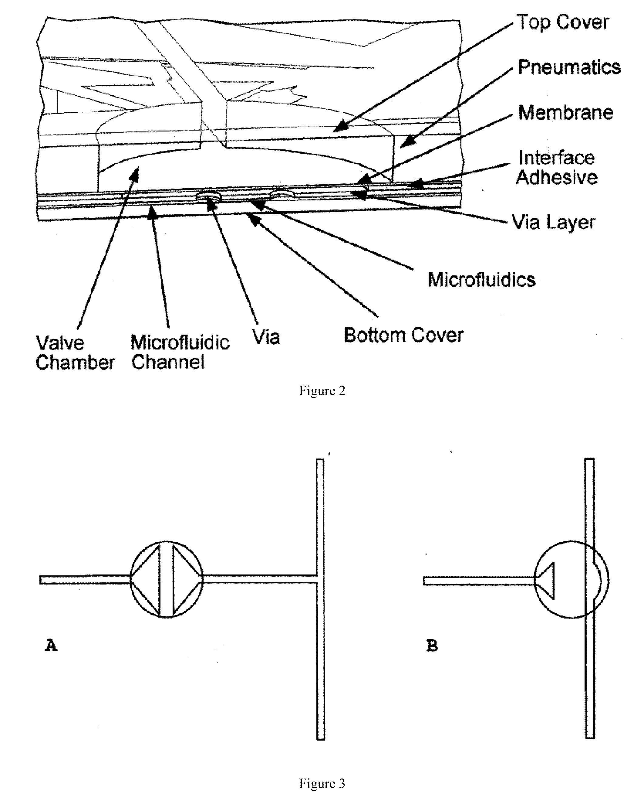
[0069]The present disclosure provides systems comprising microfluidic chip devices and thermal regulators and methods of use of the devices. The systems disclosed herein find use in the preparation and analysis of target analytes, including processing biochemical or chemical samples, the analysis of target analytes, or the recovery of processed biochemical or chemical samples for analysis in a separate device. In one aspect, the microfluidic chip device comprises a first region and a second region (FIG. 1). As depicted in FIG. 2, the first region, or microfluidics sandwich region, has multiple layers comprising a fluidics layer comprising fluidic channels; a pneumatics layer comprising pneumatic channels; and an actuation layer (e.g., an elastomeric layer) sandwiched between the fluidics layer and the pneumatic layer, wherein the sandwich comprises Micro-Robotic on-Chip Valve and Pump valves (MOVe) to regulate fluid flow in the fluidics channels. The secon...


PUM


Abstract

This invention provides microfluidic devices that comprise a fluidics layer having microfluidic channels and one or more regulating layers that regulate the movement of fluid in the channels. The microfluidic devices can be used to mix one or more fluids. At least a portion of the fluidics layer can be isolated from the regulating layer, for example in the form of a shelf. Such isolated portions can be used as areas in which the temperature of liquids is controlled. Also provided are instruments including thermal control devices into which the microfluidic device is engaged so that the thermal control device controls temperature in the isolated portion, and a movable magnetic assembly including magnets with shields so that a focused magnetic field can be applied to or withdrawn from the isolated portion or any other portion of the microfluidic device. Also provided are methods of mixing fluids. The methods include stacking a plurality of alternating boluses of different liquids in a microfluidic channel, and moving the stacked boluses through the channel. In another method, the boluses are moved into a diaphragm valve having a volume able to accommodate several boluses, and then pumping the liquids out of the valve.

Description

CROSS-REFERENCE[0001]This application claims the benefit of the filing date of the following U.S. Provisional Patent Applications: 61 / 204,179, filed Dec. 31, 2008; 61 / 205,534, filed Jan. 20, 2009; 61 / 162,080, filed Mar. 20, 2009; and 61 / 227,382, filed Jul. 21, 2009.STATEMENT AS TO FEDERALLY SPONSORED RESEARCH[0002]This invention was made with the support of the United States Government under Grant number 5R01HG003583-04 by National Institutes of Health. The Government may have rights in this invention.BACKGROUND OF THE INVENTION[0003]A variety of microfluidic devices of disparate design have been developed in the past often with the goal of reducing sample volume requirements in bioanalytical methods, integrating multiple steps into automated processes, integrating sample preparation and analysis, and connecting to the full volume world of samples and procedures.[0004]In the absence of standards controlling external dimensional form factors, the nature of the upstream and downstream...

Claims


Application Information

Patent Timeline
IPC IPC(8): B01F15/02F16L37/56F25B21/02F16K31/08F16K7/00
CPCB01F11/0045B01F13/0059F16K99/0001F16K99/0015F16K99/0036F16K99/0046F16K99/0059Y10T137/87153Y10T137/0318Y10T137/877B01F5/06B01L3/502738B01L2400/0655B01L2400/0622B01F31/31B01F33/30B01F25/40
Inventor JOVANOVICH, STEVAN B.NIELSEN, WILLIAM D.RECKNOR, MICHAELTROUNSTINE, MARY
Owner INTEGENX
Why Eureka
Try Eureka